Pages

Showing posts with label reflections. Show all posts

Thursday, July 30, 2009

Water in Your Browser

Recently I’ve been playing around with O3D. If you don’t know, O3D is Google’s new browser graphics API. It enables you to develop 3d interactive applications that run inside a browser window (and quite easily mind you). In fact it rivals XNA on getting an app up and running quickly.

And on that note, I’ve ported the water sample to O3D (minus the camera animation). Besides a bug I encountered with the sample content converter (and promptly fixed by one of the o3d developers), it was a relatively painless conversion. All that was required was to setup a scene in max, apply materials, export to collada and convert to the o3d format. Setting up the render targets also took minimal effort :). The shaders, for the most part, remained untouched.

Click the picture to have a go!

waterscene

If you’re interested in the max file or source you can get both here:

Thursday, November 13, 2008

Water Game Component


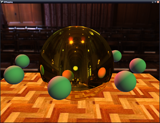
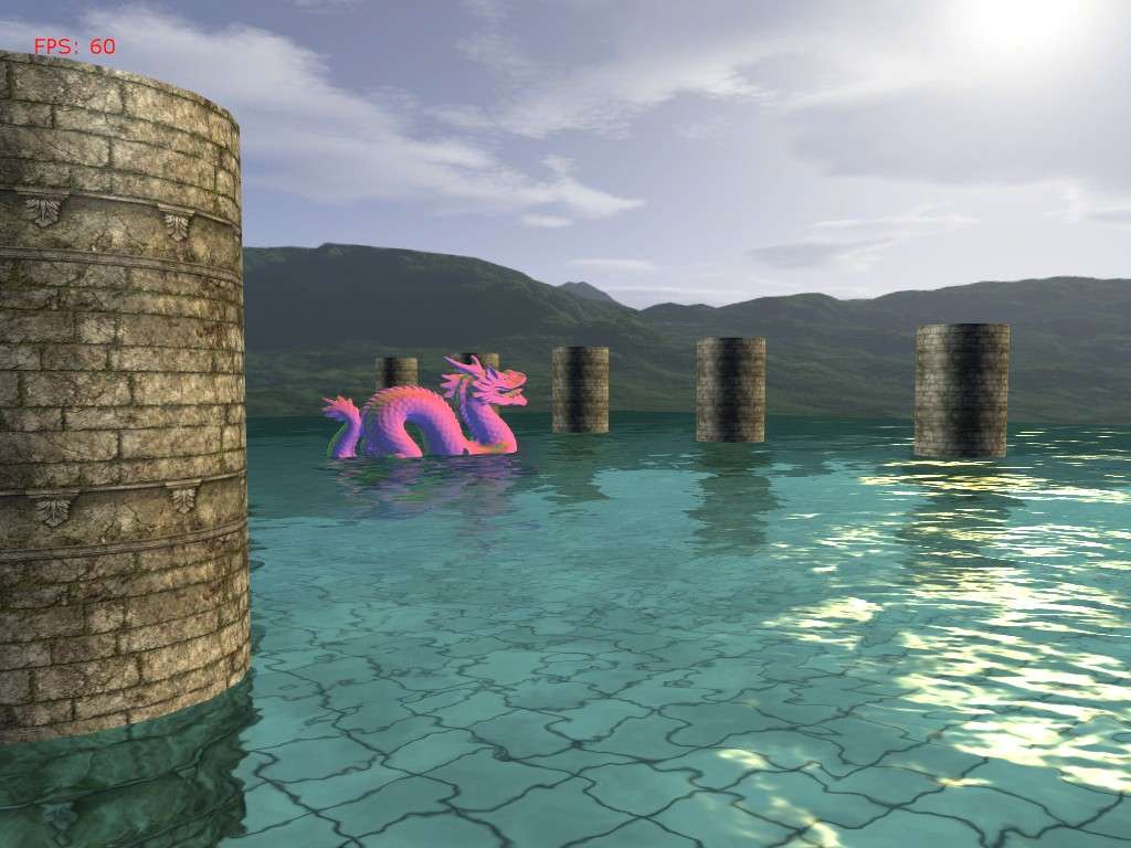
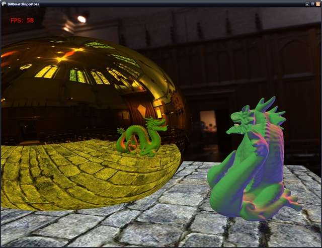
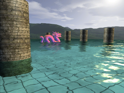
I had some requests awhile back for a more independent water effect that I had provided in my camera animation tutorials. And just the other day I remembered that I had totally forgot about this (doh!). So here is a DrawableGameComponent for the water effect. Have a look here to see it in action.

To setup the component we need to fill out a WaterOptions object that will be passed to the water component.

WaterOptions options = new WaterOptions();
options.Width = 257;
options.Height = 257;
options.CellSpacing = 0.5f;
options.WaveMapAsset0 = "Textures/wave0";
options.WaveMapAsset1 = "Textures/wave1";
options.WaveMapVelocity0 = new Vector2(0.01f, 0.03f);
options.WaveMapVelocity1 = new Vector2(-0.01f, 0.03f);
options.WaveMapScale = 2.5f;
options.WaterColor = new Vector4(0.5f, 0.79f, 0.75f, 1.0f);
options.SunColor = new Vector4(1.0f, 0.8f, 0.4f, 1.0f);
options.SunDirection = new Vector3(2.6f, -1.0f, -1.5f);
options.SunFactor = 1.5f;
options.SunPower = 250.0f;

mWaterMesh = new Water(this);
mWaterMesh.Options = options;
mWaterMesh.EffectAsset = "Shaders/Water";
mWaterMesh.World = Matrix.CreateTranslation(Vector3.UnitY * 2.0f);
mWaterMesh.RenderObjects = DrawObjects;

So here will fill out various options such as width and height, cell spacing, the normal map asset names, etc. We then create the water component, and assign it the options object. We then provide the filename of the Water.fx shader, the water's position and we then assign its RenderObjects delegate a function that will be used to draw the objects in your scene.

The component tries to be relatively independent of how your represent your game objects. All that it asks for is that you provide a function that takes a reflection matrix. This function should go through the objects that you want to be reflected/refracted and combine the reflection matrix with the object's world matrix.

Here's an example of what your DrawObjects() function might look like.
private void DrawObjects(Matrix reflMatrix)
{
foreach (DrawableGameComponent mesh in Components)
{
Matrix oldWorld = mesh.World;
mesh.World = oldWorld * reflMatrix;

mesh.Draw(mGameTime);

mesh.World = oldWorld;
}
}
mWaterMesh.RenderObjects is the delegate that has the signature of: public delegate void RenderObjects(Matrix reflectionMatrix);

Basically this function should just go through your game objects and render them.

Lastly, before you draw your objects in the scene, you need to send to the water component the ViewProjection matrix and the camera's position by using WaterMesh.SetCamera(). And you need to call WaterMesh.UpdateWaterMaps() to update the reflection and refraction maps. After this, you can clear your framebuffer and draw your objects. For how this effect looks you can take a look at my camera animation tutorials.

Water GameComponent:

using System;
using System.Collections.Generic;
using System.Text;

using Microsoft.Xna.Framework;
using Microsoft.Xna.Framework.Graphics;
using Microsoft.Xna.Framework.Content;

namespace WaterSample
{
//delegate that the water component to call to render the objects in the scene
public delegate void RenderObjects(Matrix reflectionMatrix);

/// <summary>
///
Options that must be passed to the water component before Initialization
/// </summary>
public class WaterOptions
{
//width and height must be of the form 2^n + 1
public int Width = 257;
public int Height = 257;
public float CellSpacing = .5f;

public float WaveMapScale = 1.0f;

public int RenderTargetSize = 512;

//offsets for the texcoords of the wave maps updated every frame
public Vector2 WaveMapOffset0;
public Vector2 WaveMapOffset1;

//the direction to offset the texcoords of the wave maps
public Vector2 WaveMapVelocity0;
public Vector2 WaveMapVelocity1;

//asset names for the normal/wave maps
public string WaveMapAsset0;
public string WaveMapAsset1;

public Vector4 WaterColor;
public Vector4 SunColor;
public Vector3 SunDirection;
public float SunFactor;
public float SunPower;
}

/// <summary>
///
Drawable game component for water rendering. Renders the scene to reflection and refraction
/// maps that are projected onto the water plane and are distorted based on two scrolling normal
/// maps.
/// </summary>
public class Water : DrawableGameComponent
{
#region Fields
private RenderObjects mDrawFunc;

//vertex and index buffers for the water plane
private VertexBuffer mVertexBuffer;
private IndexBuffer mIndexBuffer;
private VertexDeclaration mDecl;

//water shader
private Effect mEffect;
private string mEffectAsset;

//camera properties
private Vector3 mViewPos;
private Matrix mViewProj;
private Matrix mWorld;

//maps to render the refraction/reflection to
private RenderTarget2D mRefractionMap;
private RenderTarget2D mReflectionMap;

//scrolling normal maps that we will use as a
//a normal for the water plane in the shader
private Texture mWaveMap0;
private Texture mWaveMap1;

//user specified options to configure the water object
private WaterOptions mOptions;

//tells the water object if it needs to update the refraction
//map itself or not. Since refraction just needs the scene drawn
//regularly, we can:
// --Draw the objects we want refracted
// --Resolve the back buffer and send it to the water
// --Skip computing the refraction map in the water object
private bool mGrabRefractionFromFB = false;

private int mNumVertices;
private int mNumTris;
#endregion

#region
Properties

public RenderObjects RenderObjects
{
set { mDrawFunc = value; }
}

/// <summary>
///
Name of the asset for the Effect.
/// </summary>
public string EffectAsset
{
get { return mEffectAsset; }
set { mEffectAsset = value; }
}

/// <summary>
///
The render target that the refraction is rendered to.
/// </summary>
public RenderTarget2D RefractionMap
{
get { return mRefractionMap; }
set { mRefractionMap = value; }
}

/// <summary>
///
The render target that the reflection is rendered to.
/// </summary>
public RenderTarget2D ReflectionMap
{
get { return mReflectionMap; }
set { mReflectionMap = value; }
}

/// <summary>
///
Options to configure the water. Must be set before
/// the water is initialized. Should be set immediately
/// following the instantiation of the object.
/// </summary>
public WaterOptions Options
{
get { return mOptions; }
set { mOptions = value; }
}

/// <summary>
///
The world matrix of the water.
/// </summary>
public Matrix World
{
get { return mWorld; }
set { mWorld = value; }
}

#endregion

public
Water(Game game) : base(game)
{

}

public override void Initialize()
{
base.Initialize();

//build the water mesh
mNumVertices = mOptions.Width * mOptions.Height;
mNumTris = (mOptions.Width - 1) * (mOptions.Height - 1) * 2;
VertexPositionTexture[] vertices = new VertexPositionTexture[mNumVertices];

Vector3[] verts;
int[] indices;

GenTriGrid(mOptions.Height, mOptions.Width, mOptions.CellSpacing, mOptions.CellSpacing,
Vector3.Zero, out verts, out indices);

//copy the verts into our PositionTextured array
for (int i = 0; i < mOptions.Width; ++i)
{
for (int j = 0; j < mOptions.Height; ++j)
{
int index = i * mOptions.Width + j;
vertices[index].Position = verts[index];
vertices[index].TextureCoordinate = new Vector2((float)j / mOptions.Width, (float)i / mOptions.Height);
}
}

mVertexBuffer = new VertexBuffer(Game.GraphicsDevice,
VertexPositionTexture.SizeInBytes * mOptions.Width * mOptions.Height,
BufferUsage.WriteOnly);
mVertexBuffer.SetData(vertices);

mIndexBuffer = new IndexBuffer(Game.GraphicsDevice, typeof(int), indices.Length, BufferUsage.WriteOnly);
mIndexBuffer.SetData(indices);

mDecl = new VertexDeclaration(Game.GraphicsDevice, VertexPositionTexture.VertexElements);
}

protected override void LoadContent()
{
base.LoadContent();

mWaveMap0 = Game.Content.Load<Texture2D>(mOptions.WaveMapAsset0);
mWaveMap1 = Game.Content.Load<Texture2D>(mOptions.WaveMapAsset1);

PresentationParameters pp = Game.GraphicsDevice.PresentationParameters;
SurfaceFormat format = pp.BackBufferFormat;
MultiSampleType msType = pp.MultiSampleType;
int msQuality = pp.MultiSampleQuality;

mRefractionMap = new RenderTarget2D(Game.GraphicsDevice, mOptions.RenderTargetSize, mOptions.RenderTargetSize,
1, format, msType, msQuality);
mReflectionMap = new RenderTarget2D(Game.GraphicsDevice, mOptions.RenderTargetSize, mOptions.RenderTargetSize,
1, format, msType, msQuality);

mEffect = Game.Content.Load<Effect>(mEffectAsset);

//set the parameters that shouldn't change.
//Some of these might need to change every once in awhile,
//move them to updateEffectParams if you need that functionality.
if (mEffect != null)
{
mEffect.Parameters["WaveMap0"].SetValue(mWaveMap0);
mEffect.Parameters["WaveMap1"].SetValue(mWaveMap1);

mEffect.Parameters["TexScale"].SetValue(mOptions.WaveMapScale);

mEffect.Parameters["WaterColor"].SetValue(mOptions.WaterColor);
mEffect.Parameters["SunColor"].SetValue(mOptions.SunColor);
mEffect.Parameters["SunDirection"].SetValue(mOptions.SunDirection);
mEffect.Parameters["SunFactor"].SetValue(mOptions.SunFactor);
mEffect.Parameters["SunPower"].SetValue(mOptions.SunPower);

mEffect.Parameters["World"].SetValue(mWorld);
}
}

public override void Update(GameTime gameTime)
{
float timeDelta = (float)gameTime.ElapsedGameTime.TotalSeconds;

mOptions.WaveMapOffset0 += mOptions.WaveMapVelocity0 * timeDelta;
mOptions.WaveMapOffset1 += mOptions.WaveMapVelocity1 * timeDelta;

if (mOptions.WaveMapOffset0.X >= 1.0f mOptions.WaveMapOffset0.X <= -1.0f)
mOptions.WaveMapOffset0.X = 0.0f;
if (mOptions.WaveMapOffset1.X >= 1.0f mOptions.WaveMapOffset1.X <= -1.0f)
mOptions.WaveMapOffset1.X = 0.0f;
if (mOptions.WaveMapOffset0.Y >= 1.0f mOptions.WaveMapOffset0.Y <= -1.0f)
mOptions.WaveMapOffset0.Y = 0.0f;
if (mOptions.WaveMapOffset1.Y >= 1.0f mOptions.WaveMapOffset1.Y <= -1.0f)
mOptions.WaveMapOffset1.Y = 0.0f;
}

public override void Draw(GameTime gameTime)
{
UpdateEffectParams();

Game.GraphicsDevice.Indices = mIndexBuffer;
Game.GraphicsDevice.Vertices[0].SetSource(mVertexBuffer, 0, VertexPositionTexture.SizeInBytes);
Game.GraphicsDevice.VertexDeclaration = mDecl;

mEffect.Begin(SaveStateMode.None);

foreach (EffectPass pass in mEffect.CurrentTechnique.Passes)
{
pass.Begin();
Game.GraphicsDevice.DrawIndexedPrimitives(PrimitiveType.TriangleList, 0, 0, mNumVertices, 0, mNumTris);
pass.End();
}

mEffect.End();
}

/// <summary>
///
Set the ViewProjection matrix and position of the Camera.
/// </summary>
/// <param name="viewProj"></param>
/// <param name="pos"></param>
public void SetCamera(Matrix viewProj, Vector3 pos)
{
mViewProj = viewProj;
mViewPos = pos;
}

/// <summary>
///
Updates the reflection and refraction maps. Called
/// on update.
/// </summary>
/// <param name="gameTime"></param>
public void UpdateWaterMaps(GameTime gameTime)
{
/*------------------------------------------------------------------------------------------
* Render to the Reflection Map
*/
//clip objects below the water line, and render the scene upside down
GraphicsDevice.RenderState.CullMode = CullMode.CullClockwiseFace;

GraphicsDevice.SetRenderTarget(0, mReflectionMap);
GraphicsDevice.Clear(ClearOptions.Target ClearOptions.DepthBuffer, mOptions.WaterColor, 1.0f, 0);

//reflection plane in local space
Vector4 waterPlaneL = new Vector4(0.0f, -1.0f, 0.0f, 0.0f);

Matrix wInvTrans = Matrix.Invert(mWorld);
wInvTrans = Matrix.Transpose(wInvTrans);

//reflection plane in world space
Vector4 waterPlaneW = Vector4.Transform(waterPlaneL, wInvTrans);

Matrix wvpInvTrans = Matrix.Invert(mWorld * mViewProj);
wvpInvTrans = Matrix.Transpose(wvpInvTrans);

//reflection plane in homogeneous space
Vector4 waterPlaneH = Vector4.Transform(waterPlaneL, wvpInvTrans);

GraphicsDevice.ClipPlanes[0].IsEnabled = true;
GraphicsDevice.ClipPlanes[0].Plane = new Plane(waterPlaneH);

Matrix reflectionMatrix = Matrix.CreateReflection(new Plane(waterPlaneW));

if (mDrawFunc != null)
mDrawFunc(reflectionMatrix);

GraphicsDevice.RenderState.CullMode = CullMode.CullCounterClockwiseFace;

GraphicsDevice.SetRenderTarget(0, null);


/*------------------------------------------------------------------------------------------
* Render to the Refraction Map
*/

//if the application is going to send us the refraction map
//exit early. The refraction map must be given to the water component
//before it renders
if (mGrabRefractionFromFB)
{
GraphicsDevice.ClipPlanes[0].IsEnabled = false;
return;
}

//update the refraction map, clip objects above the water line
//so we don't get artifacts
GraphicsDevice.SetRenderTarget(0, mRefractionMap);
GraphicsDevice.Clear(ClearOptions.Target ClearOptions.DepthBuffer, mOptions.WaterColor, 1.0f, 1);

//reflection plane in local space
waterPlaneL.W = 2.5f;

//if we're below the water line, don't perform clipping.
//this allows us to see the distorted objects from under the water
if (mViewPos.Y < mWorld.Translation.Y)
{
GraphicsDevice.ClipPlanes[0].IsEnabled = false;
}

if (mDrawFunc != null)
mDrawFunc(Matrix.Identity);

GraphicsDevice.ClipPlanes[0].IsEnabled = false;

GraphicsDevice.SetRenderTarget(0, null);
}

/// <summary>
///
Updates effect parameters related to the water shader
/// </summary>
private void UpdateEffectParams()
{
//update the reflection and refraction textures
mEffect.Parameters["ReflectMap"].SetValue(mReflectionMap.GetTexture());
mEffect.Parameters["RefractMap"].SetValue(mRefractionMap.GetTexture());

//normal map offsets
mEffect.Parameters["WaveMapOffset0"].SetValue(mOptions.WaveMapOffset0);
mEffect.Parameters["WaveMapOffset1"].SetValue(mOptions.WaveMapOffset1);

mEffect.Parameters["WorldViewProj"].SetValue(mWorld * mViewProj);

mEffect.Parameters["EyePos"].SetValue(mViewPos);
}

/// <summary>
///
Generates a grid of vertices to use for the water plane.
/// </summary>
/// <param name="numVertRows">
Number of rows. Must be 2^n + 1. Ex. 129, 257, 513.</param>
/// <param name="numVertCols">
Number of columns. Must be 2^n + 1. Ex. 129, 257, 513.</param>
/// <param name="dx">
Cell spacing in the x dimension.</param>
/// <param name="dz">
Cell spacing in the y dimension.</param>
/// <param name="center">
Center of the plane.</param>
/// <param name="verts">
Outputs the constructed vertices for the plane.</param>
/// <param name="indices">
Outpus the constructed triangle indices for the plane.</param>
private void GenTriGrid(int numVertRows, int numVertCols, float dx, float dz,
Vector3 center, out Vector3[] verts, out int[] indices)
{
int numVertices = numVertRows * numVertCols;
int numCellRows = numVertRows - 1;
int numCellCols = numVertCols - 1;

int mNumTris = numCellRows * numCellCols * 2;

float width = (float)numCellCols * dx;
float depth = (float)numCellRows * dz;

//===========================================
// Build vertices.

// We first build the grid geometry centered about the origin and on
// the xz-plane, row-by-row and in a top-down fashion. We then translate
// the grid vertices so that they are centered about the specified
// parameter 'center'.

//verts.resize(numVertices);
verts = new Vector3[numVertices];

// Offsets to translate grid from quadrant 4 to center of
// coordinate system.
float xOffset = -width * 0.5f;
float zOffset = depth * 0.5f;

int k = 0;
for (float i = 0; i < numVertRows; ++i)
{
for (float j = 0; j < numVertCols; ++j)
{
// Negate the depth coordinate to put in quadrant four.
// Then offset to center about coordinate system.
verts[k] = new Vector3(0, 0, 0);
verts[k].X = j * dx + xOffset;
verts[k].Z = -i * dz + zOffset;
verts[k].Y = 0.0f;

Matrix translation = Matrix.CreateTranslation(center);
verts[k] = Vector3.Transform(verts[k], translation);

++k; // Next vertex
}
}

//===========================================
// Build indices.

//indices.resize(mNumTris * 3);
indices = new int[mNumTris * 3];

// Generate indices for each quad.
k = 0;
for (int i = 0; i < numCellRows; ++i)
{
for (int j = 0; j < numCellCols; ++j)
{
indices[k] = i * numVertCols + j;
indices[k + 1] = i * numVertCols + j + 1;
indices[k + 2] = (i + 1) * numVertCols + j;

indices[k + 3] = (i + 1) * numVertCols + j;
indices[k + 4] = i * numVertCols + j + 1;
indices[k + 5] = (i + 1) * numVertCols + j + 1;

// next quad
k += 6;
}
}
}
}
}

Water.fx shader:

//Water effect shader that uses reflection and refraction maps projected onto the water.
//These maps are distorted based on the two scrolling normal maps.

float4x4 World;
float4x4 WorldViewProj;

float4 WaterColor;
float3 SunDirection;
float4 SunColor;
float SunFactor; //the intensity of the sun specular term.
float SunPower; //how shiny we want the sun specular term on the water to be.
float3 EyePos;

// Texture coordinate offset vectors for scrolling
// normal maps.
float2 WaveMapOffset0;
float2 WaveMapOffset1;

// Two normal maps and the reflection/refraction maps
texture WaveMap0;
texture WaveMap1;
texture ReflectMap;
texture RefractMap;

//scale used on the wave maps
float TexScale;

static const float R0 = 0.02037f;

sampler WaveMapS0 = sampler_state
{
Texture = <WaveMap0>;
MinFilter = LINEAR;
MagFilter = LINEAR;
MipFilter = LINEAR;
AddressU = WRAP;
AddressV = WRAP;
};

sampler WaveMapS1 = sampler_state
{
Texture = <WaveMap1>;
MinFilter = LINEAR;
MagFilter = LINEAR;
MipFilter = LINEAR;
AddressU = WRAP;
AddressV = WRAP;
};

sampler ReflectMapS = sampler_state
{
Texture = <ReflectMap>;
MinFilter = LINEAR;
MagFilter = LINEAR;
MipFilter = LINEAR;
AddressU = CLAMP;
AddressV = CLAMP;
};

sampler RefractMapS = sampler_state
{
Texture = <RefractMap>;
MinFilter = LINEAR;
MagFilter = LINEAR;
MipFilter = LINEAR;
AddressU = CLAMP;
AddressV = CLAMP;
};

struct OutputVS
{
float4 posH : POSITION0;
float3 toEyeW : TEXCOORD0;
float2 tex0 : TEXCOORD1;
float2 tex1 : TEXCOORD2;
float4 projTexC : TEXCOORD3;
float4 pos : TEXCOORD4;
};

OutputVS WaterVS( float3 posL : POSITION0,
float2 texC : TEXCOORD0)
{
// Zero out our output.
OutputVS outVS = (OutputVS)0;

// Transform vertex position to world space.
float3 posW = mul(float4(posL, 1.0f), World).xyz;
outVS.pos.xyz = posW;
outVS.pos.w = 1.0f;

// Compute the unit vector from the vertex to the eye.
outVS.toEyeW = posW - EyePos;

// Transform to homogeneous clip space.
outVS.posH = mul(float4(posL, 1.0f), WorldViewProj);

// Scroll texture coordinates.
outVS.tex0 = (texC * TexScale) + WaveMapOffset0;
outVS.tex1 = (texC * TexScale) + WaveMapOffset1;

// Generate projective texture coordinates from camera's perspective.
outVS.projTexC = outVS.posH;

// Done--return the output.
return outVS;
}

float4 WaterPS( float3 toEyeW : TEXCOORD0,
float2 tex0 : TEXCOORD1,
float2 tex1 : TEXCOORD2,
float4 projTexC : TEXCOORD3,
float4 pos : TEXCOORD4) : COLOR
{
projTexC.xyz /= projTexC.w;
projTexC.x = 0.5f*projTexC.x + 0.5f;
projTexC.y = -0.5f*projTexC.y + 0.5f;
projTexC.z = .1f / projTexC.z;

toEyeW = normalize(toEyeW);
SunDirection = normalize(SunDirection);

// Light vector is opposite the direction of the light.
float3 lightVecW = -SunDirection;

// Sample normal map.
float3 normalT0 = tex2D(WaveMapS0, tex0);
float3 normalT1 = tex2D(WaveMapS1, tex1);

//unroll the normals retrieved from the normalmaps
normalT0.yz = normalT0.zy;
normalT1.yz = normalT1.zy;

normalT0 = 2.0f*normalT0 - 1.0f;
normalT1 = 2.0f*normalT1 - 1.0f;

float3 normalT = normalize(0.5f*(normalT0 + normalT1));
float3 n1 = float3(0,1,0); //we'll just use the y unit vector for spec reflection.

//get the reflection vector from the eye
float3 R = normalize(reflect(toEyeW,normalT));

float4 finalColor;
finalColor.a = 1;

//compute the fresnel term to blend reflection and refraction maps
float ang = saturate(dot(-toEyeW,n1));
float f = R0 + (1.0f-R0) * pow(1.0f-ang,5.0);

//also blend based on distance
f = min(1.0f, f + 0.007f * EyePos.y);

//compute the reflection from sunlight, hacked in color, should be a variable
float sunFactor = SunFactor;
float sunPower = SunPower;

if(EyePos.y < pos.y)
{
sunFactor = 7.0f; //these could also be sent to the shader
sunPower = 55.0f;
}
float3 sunlight = sunFactor * pow(saturate(dot(R, lightVecW)), sunPower) * SunColor;

float4 refl = tex2D(ReflectMapS, projTexC.xy + projTexC.z * normalT.xz);
float4 refr = tex2D(RefractMapS, projTexC.xy - projTexC.z * normalT.xz);

//only use the refraction map if we're under water
if(EyePos.y < pos.y)
f = 0.0f;

//interpolate the reflection and refraction maps based on the fresnel term and add the sunlight
finalColor.rgb = WaterColor * lerp( refr, refl, f) + sunlight;

return finalColor;
}

technique WaterTech
{
pass Pass1
{
// Specify the vertex and pixel shader associated with this pass.
vertexShader = compile vs_2_0 WaterVS();
pixelShader = compile ps_2_0 WaterPS();

CullMode = None;
}
}

Edit: A demo of the water component is now available.

Wednesday, July 16, 2008

Dual-Paraboloid Reflections

dragon

I recently had to investigate dual-paraboloid reflections at work for an unnamed console. What are these you ask? Great question! :) Lets start with some background.

The standard way of calculating reflections is to use an environment map, more specifically a cube map. In my last tutorial on reflections, this basic type of reflection mapping was used to compare against billboard impostor reflections. Now, cubemaps are great for static scenes, and are relatively low cost to perform a texture fetch on in a shader. However if you have a dynamic scene you have to update all 6 sides of the cubemap (this is not technically true, aggressive culling and other optimizations can guarantee at most 5 sides). Holy crap, now we have to render our scene 6 times!

This is where dual-paraboloid reflections come in. They are a view-independent method of rendering reflections just like cubemaps. Except you only have to update 2 textures, not 6! The downside is that you are going to lose quality for speed, but unless you have to have high-quality reflections, paraboloid reflections will probably provide sufficient results.

Reference articles:

View-Independent Environment Maps

Shadow Mapping for Hemispherical and Omnidirectional Light Sources

Dual Paraboloid Mapping in the Vertex Shader

In the interest of keeping this post from getting too long, I won't go into great detail on the mathematical process. I suggest you refer to the first and third papers for an in-depth discussion on the details.

Now lets move on to what exactly paraboloid mapping is. Lets look at what a paraboloid is.

paraboloid

The basic idea is that for any origin O, we can divide the scene into two hemispheres, front and rear. For each of these hemispheres there exists a paraboloid surface that will focus any ray traveling in the direction of O into the direction of the the hemisphere. Here is a 2d picture demonstrating the idea:

paraboloid2d

A brief math overview:

What we need to find is the intersection point where the incident ray intersects the paraboloid surface. To do this we need to know the incident ray and the reflected ray. Now because the paraboloid reflects rays in the same direction, it is easy to compute the reflection vector: it's the forward direction of the hemisphere! So the front hemisphere's reflection vector will always be <0, 0, 1> and the rear hemisphere's reflection vector will always be <0, 0, -1>. Easy! And the incident ray is calculated the same as with environment mapping by reflecting the ray from the pixel position to the eye across the normal of the 3D pixel.

Now all we have to do is find the normal of the intersection which we will use to map our vertices into paraboloid space. To find the normal, we add the incident and reflected vectors and divide the x and y components by the z value.

Generating the Paraboloid maps:

What we are basically going to do is, in the vertex shader, place each vertex ourselves that has been distorted by the paraboloid. First we need to transform the vertex by the view matrix of the paraboloid 'camera'. We don't apply the projection matrix since we're going to place the point ourselves

output.Position = mul(input.Position, WorldViewProj);

Next we need to find the vector from the the vertex to the origin of the paraboloid, which is simply:

float L = length( output.Position.xyz );
output.Position = output.Position / L;

Now we need to find the x and y coordinates of the point where the incident ray intersects the paraboloid surface.

output.Position.z = output.Position.z + 1;
output.Position.x = output.Position.x / output.Position.z;
output.Position.y = output.Position.y / output.Position.z;

Finally we set the z value as the distance from the vertex to the origin of the paraboloid, scaled and biased by the near and far planes of the paraboloid 'camera'.

output.Position.z = (L - NearPlane) / (FarPlane - NearPlane);
output.Position.w = 1;

And the only thing we need to add in the pixel shader is to make sure and clip vertices that are behind the viewpoint using the intrinsic clip() function of HLSL.


front

frontWF

Reflections with paraboloid maps:

In the reflection pixel shader we will: generate the reflection vector the same way as cube mapping, generate texture coordinates for both the front and rear paraboloids' textures, and blend the samples taken from the textures.

The texture coordinates are generated exactly as how we generated them before in the generation step. We also scale and bias them to correctly index a D3D texture. And then we take a sample from each map and pick the sample with the greater color value:

// calculate the front paraboloid map texture coordinates
float2 front;
front.x = R.x / (R.z + 1);
front.y = R.y / (R.z + 1);
front.x = .5f * front.x + .5f; //bias and scale to correctly sample a d3d texture
front.y = -.5f * front.y + .5f;

// calculate the back paraboloid map texture coordinates
float2 back;
back.x = R.x / (1 - R.z);
back.y = R.y / (1 - R.z);
back.x = .5f * back.x + .5f; //bias and scale to correctly sample a d3d texture
back.y = -.5f * back.y + .5f;

float4 forward = tex2D( FrontTex, front ); // sample the front paraboloid map
float4 backward = tex2D( BackTex, back ); // sample the back paraboloid map

float4 finalColor = max(forward, backward);

ss1

Optimizations:

If you align the paraboloid 'camera' such that it is always facing down the +/- z axis, you don't need to transform the vertices by the view matrix of the camera. You only need to do a simple translation of the vertex by the camera position.

Conclusion:

As you can see, paraboloid maps give pretty good results. The won't give you the quality of cubemaps, but they are faster to update and require less memory. And in the console world, requiring less is almost reason enough to pick this method over cubemaps.

One drawback of paraboloid maps is that the environment geometry has to be sufficiently tessellated or will we will have noticeable artifacts on our reflector. Another drawback is that on spherical objects we will see seems. However with objects that are reasonably complex (such as the Stanford bunny or dragon) and are not simple shapes, the seams will not be as noticeable.

Next time I will present dual-paraboloid mapping for use with real-time omnidirectional shadow mapping of point lights.

Saturday, May 3, 2008

Camera Animation, Part II

Camera Animation with a cubic spline:


So last time I lied a little bit about our camera path. I showed this picture:


to describe the path that we wanted. But with linear interpolation, what we really ended up with was something like:


But today, I'll introduce cubic spline interpolation, and this will produce a truly smooth curve. Most of the code is the same, the only thing that has changed is that I have added a cubic option to the build function and have changed the animation to be reliant on time.

Building the natural cubic spline is more math intensive than with linear interpolation, so to start out here's a few links on cubic splines:

//a point on a cubic spline is affected by every other point
//so we need to build the cubic equations for each control point
//by looking at the entire curve. This is what calculateCubicSpline does
Vector3[] looks = new Vector3[mKeyFrames.Count];
Vector3[] positions = new Vector3[mKeyFrames.Count];
Vector3[] ups = new Vector3[mKeyFrames.Count];

for (int i = 0; i < mKeyFrames.Count; i++)
{
looks[i] = mKeyFrames[i].Look;
positions[i] = mKeyFrames[i].Position;
ups[i] = mKeyFrames[i].Up;
}

Cubic[] pos_cubic = calculateCubicSpline(mKeyFrames.Count - 1, positions);
Cubic[] look_cubic = calculateCubicSpline(mKeyFrames.Count - 1, looks);
Cubic[] up_cubic = calculateCubicSpline(mKeyFrames.Count - 1, ups);

for (int i = 0; i < mKeyFrames.Count - 1; i++)
{
for (int j = 0; j < mPathSteps; j++)
{
float k = (float)j / (float)(mPathSteps - 1);

Vector3 center = pos_cubic[i].GetPointOnSpline(k);
Vector3 up = up_cubic[i].GetPointOnSpline(k);
Vector3 look = look_cubic[i].GetPointOnSpline(k);

Vector3 r = Vector3.Cross(up, look);
Vector3 u = Vector3.Cross(look, r * -1f);

Camera cam = new Camera();
cam.SetLens(mFOV, mAspect, mNearZ, mFarZ);
cam.Place(center, look, u);

cam.BuildView();

mCameraPath.Add(cam);
}
}
So the first thing we do is build the cubic polynomials for each control point. And because each point controls the shape of the spline, we have to consider each point when building the polynomials. In this way, it is very different from linear interpolation in that we have to know information about the whole curve to perform a cubic interpolation rather than just the current and next control point as with linear interpolation. You might be thinking that "well Vector3 already contains a SmoothStep function that performs cubic interpolation". And you're right it does, but just interpolating the two points without knowledge of the whole curve still produces segmented(i.e. not smooth) animation. Once we have the polynomials for each control point, we can perform a cubic interpolation by just looking at the current and next control point, in the same fashion that we did with linear interpolation.

This is what the calculateCubicSpline function does, it builds polynomials for each control point, successively building off of the last control point's polynomial. Let's look at it:

Vector3[] gamma = new Vector3[n + 1];
Vector3[] delta = new Vector3[n + 1];
Vector3[] D = new Vector3[n + 1];
int i;
/* We need to solve the equation
* taken from: http://mathworld.wolfram.com/CubicSpline.html
[2 1 ] [D[0]] [3(v[1] - v[0]) ]
: 1 4 1 : :D[1]: :3(v[2] - v[0]) :
: 1 4 1 : : . : = : . :
: ..... : : . : : . :
: 1 4 1: : . : :3(v[n] - v[n-2]):
[ 1 2] [D[n]] [3(v[n] - v[n-1])]

by converting the matrix to upper triangular.
The D[i] are the derivatives at the control points.
*/

//this builds the coefficients of the left matrix
gamma[0] = Vector3.Zero;
gamma[0].X = 1.0f / 2.0f;
gamma[0].Y = 1.0f / 2.0f;
gamma[0].Z = 1.0f / 2.0f;
for (i = 1; i < n; i++)
{
gamma[i] = Vector3.One / ((4 * Vector3.One) - gamma[i - 1]);
}
gamma[n] = Vector3.One / ((2 * Vector3.One) - gamma[n - 1]);

delta[0] = 3 * (v[1] - v[0]) * gamma[0];
for (i = 1; i < n; i++)
{
delta[i] = (3 * (v[i + 1] - v[i - 1]) - delta[i - 1]) * gamma[i];
}
delta[n] = (3 * (v[n] - v[n - 1]) - delta[n - 1]) * gamma[n];

D[n] = delta[n];
for (i = n - 1; i >= 0; i--)
{
D[i] = delta[i] - gamma[i] * D[i + 1];
}

// now compute the coefficients of the cubics
Cubic[] C = new Cubic[n];
for (i = 0; i < n; i++)
{
C[i] = new Cubic(v[i], D[i], 3 * (v[i + 1] - v[i]) - 2 * D[i] - D[i + 1],
2 * (v[i] - v[i + 1]) + D[i] + D[i + 1]);
}
return C;
Once we find the cubic equation for each control point (key frame), we can use GetPointOnSpline() uses the cubic equation to calculate the intermediate point along the cubic spline.

public Vector3 GetPointOnSpline(float s)
{
return (((d * s) + c) * s + b) * s + a;
}
And that's it. Now we have a smooth animation of our camera. There are many more ways to calculate the curve, including: hermite curves, b-splines, bezier curves, catmull-rom splines, NURBS(Nonuniform Rational B-Splines) and others. Microsoft also has a sample on creating a camera path that appears to be using hermite curves. But they hide all the details from you, and it's just more interesting to know the math behind it isn't it ;) ?

Thursday, May 1, 2008

Camera Animation, Part I


Due to the video being such high frequency, the blogger, youtube video compressors always make the video look like crap. Original can be found here:


So today I'll be giving a tutorial/sample on cut-scene animation, more specifically camera animation. This will be a 2 part tutorial, and this one will focus on linear interpolation of camera key frames.

So what are key frames? Key frames are the control points of an animation. They are the main/key points that you specifically define where the camera should be, and everything else in between is interpolated. You can also think of them as an outline of what the animation should look like. Here's a picture to help describe what I'm talking about.

camerapathhn1


Here, the green line is the path we want to follow, the orange dots are our key frames, and the red dots are the intermediate cameras that we want to generate.

So how do we create these intermediate cameras?

for (int i = 0; i < mKeyFrames.Count - 1; i++)
{
for (int j = 0; j < mPathSteps; j++)
{
//We could alternatively use the Vector3.lerp function
//but I wanted to show the math behind performing the linear interpolation

Vector3 diff = mKeyFrames[i + 1].Position - mKeyFrames[i].Position;
diff = Vector3.Multiply(diff, (float)j / (float)(mPathSteps - 1));
Vector3 center = mKeyFrames[i].Position + diff;

diff = mKeyFrames[i + 1].Look - mKeyFrames[i].Look;
diff = Vector3.Multiply(diff, (float)j / (float)(mPathSteps - 1));
Vector3 look = mKeyFrames[i].Look + diff;

diff = (mKeyFrames[i + 1].Up - mKeyFrames[i].Up);
diff = Vector3.Multiply(diff, (float)j / (float)(mPathSteps - 1));
Vector3 up = mKeyFrames[i].Up + diff;

Vector3 r = Vector3.Cross(up, look);
Vector3 u = Vector3.Cross(look, r * -1f);

Camera cam = new Camera();
cam.SetLens(mFOV, mAspect, mNearZ, mFarZ);
cam.Place(center, look, u);

cam.BuildView();

mCameraPath.Add(cam);
}
}
Pretty self explanatory, a basic linear interpolation. XNA is handy in that we can cut out all of that code and just use Vector3.Lerp().

The included demo has a pre defined path that is shown in the video. But you can also create your own path at run-time. Here are the controls:

  • 1 - Default camera view
  • 2 - Play the camera animation
  • 3 - Rewind the camera animation
  • 4 - Pause the camera animation
  • C - Clear the current key frames
  • K - Add the current camera to the key frames list
  • B - Build the camera path from the current key frames
  • O - Save the current key frames to an XML file

When you start the demo, the predefined path is already loaded, all you have to do is hit '2', and it will play. If you want to make your own path first clear the key frames by pressing 'C', and then navigate to where you want to be along your path and press 'K' to add your key frames. Once you're happy with your path, press 'B' to build the camera animation, and then you can play it by pressing '2'. Normally, I would use winForms or a GUI such as neoforce for the controls, but this adds a lot of clutter.

So there's probably one thing that you might notice about the camera animation, and that is that it's not very smooth. Next time I will introduce cubic interpolation to smooth out the animation.

Thursday, April 17, 2008

Reflections with Billboard Impostors

Last time I mentioned that I would post a tutorial on generating reflections using billboard impostors, well here it is. Amidst the craziness of school right now, I've found time (or rather worked on this since it's more fun) to write up this tutorial. So lets get started.

Some prerequisites for this tutorial:

  • Shader Model 3.0 compliant graphics card
  • Experience with RenderTargets
  • Experience with Custom Content Processors (not too important, I just won't go over these specifically)

Anyways, Shawn Hargreaves posted about using environment maps for reflections a few weeks ago. But we're going to take it one step further and use impostors as well as the environment map for reflections. The main problem with environment mapped refections is that everything is assumed to be infinitely far away, and thus objects appear distorted and don't intersect with geometry correctly. Using billboarded impostors tries to alleviate some of this problem by taking the reflected rays and intersecting them with billboards of the scene geometry.

So here's a couple of images to demonstrate the limitations of environment mapping.

Environment mapping:


As you can see the sphere looks like it's floating above the quad when it is actually intersecting it. Also, the dragon's reflection is too far away in the reflection.


Impostors:


Now with the impostors, the reflection of the dragon is much more accurate, and the sphere now correctly intersects the floor quad.

The details:
First we want to render each diffuse object from the reflector's point of view. So we first get the bounding box corners of the impostor geometry and setup the camera to be positioned at the center of the reflector, and looking at the center of the diffuse geometry.


// Get the 8 corners of the bounding box and transform by the world matrix
Vector3[] corners = new Vector3[8];
Vector3.Transform(mBoundBox.GetCorners(), ref mWorld, corners);

// Get the transformed center of the mesh
// alternatively, we could use mBoundingSphere.Center as sometimes it works better
Vector3 meshCenter = Center;

// The quad is a special case. Since it's so much bigger than the reflector
// we have to make sure that our camera is looking straight at the quad and
// not it's center or we'll get a distorted view of the quad.
if (mMeshType == MeshType.Quad)
{
meshCenter.X = reflectorCenter.X;
meshCenter.Z = reflectorCenter.Z;
}

// Construct a camera to render our impostor
Camera impostorCam = new Camera(camera);

// Set the camera to be at the center of the reflector and to look at the diffuse mesh
impostorCam.LookAt(reflectorCenter, meshCenter);
impostorCam.BuildView();


Next we want to project these corners to screen space and find the bounding box that fits around these projected corners:

// Now we project the vertices to screen space, so we can find the AABB of the screen
// space vertices
Vector3[] screenVerts = new Vector3[8];
for (int i = 0; i < 8; i++)
{
screenVerts[i] = mGraphicsDevice.Viewport.Project(corners[i],
impostorCam.Projection, impostorCam.View, mWorld);
}

// compute the screen space AABB
Vector3 min, max;
ComputeBoundingBoxFromPoints(screenVerts, out min, out max);

// construct the quad that will represent our diffuse mesh
Vector3[] screenQuadVerts = new Vector3[4];
screenQuadVerts[0] = new Vector3(min.X, min.Y, min.Z);
screenQuadVerts[1] = new Vector3(max.X, min.Y, min.Z);
screenQuadVerts[2] = new Vector3(max.X, max.Y, min.Z);
screenQuadVerts[3] = new Vector3(min.X, max.Y, min.Z);


Now we want to unproject these screen space vertices into world space so that we can form a 3D impostor quad of our geometry. We will use this quad later in the reflection shader for a reflective object.

We also render our diffuse object to a RenderTarget that will be the texture for our impostor quad. To do this, we setup an Orthographic Projection so that we don't have any of the perspective distortion that comes with a regular perspective projection matrix. We clear the scene with zero alpha, and we render the impostor with full alpha so that we only capture the diffuse object and nothing else.


//now unproject the screen space quad and save the
//vertices for when we render the impostor quad
for (int i = 0; i < 4; i++)
{
mImpostorVerts[i] = mGraphicsDevice.Viewport.Unproject(screenQuadVerts[i],
impostorCam.Projection, impostorCam.View, mWorld);
}

//compute the center of the quad
mImpostorCenter = Vector3.Zero;
mImpostorCenter = mImpostorVerts[0] + mImpostorVerts[1] + mImpostorVerts[2] + mImpostorVerts[3];
mImpostorCenter *= .25f;

// calculate the width and height of the imposter's vertices
float width = (mImpostorVerts[1] - mImpostorVerts[0]).Length() * 1.2f;
float height = (mImpostorVerts[3] - mImpostorVerts[0]).Length() * 1.2f;

// We construct an Orthographic projection to get rid of the projection distortion
// which we don't want for our impostor texture
impostorCam.Projection = Matrix.CreateOrthographic(width, height, .1f, 100);
impostorCam.BuildView();

//save the WorldViewProjection matrix so we can use it in the shader
mWorldViewProj = impostorCam.ViewProj;

mGraphicsDevice.SetRenderTarget(0, mRenderTarget);
mGraphicsDevice.Clear(ClearOptions.Target, new Color(1, 0, 0, 0), 1.0f, 1);

Draw(impostorCam);

mGraphicsDevice.SetRenderTarget(0, null);


// finally, compute the normal for the impostor quad, and push the vertices
// back to the center of the diffuse mesh
Vector3 trans = meshCenter - mImpostorCenter;
for (int i = 0; i < 4; ++i)
{
mImpostorVerts[i] += trans;
}

mNormal = impostorCam.Look;


Here's our resulting impostor image:


Now that we have constructed our impostor quad, it's time to render our reflective object. Here's the pixel shader code that we will use to do this:

float4 PixelShaderFunction(VertexShaderOutput input) : COLOR0
{
input.NormalW = normalize(input.NormalW);

float3 fromEyeW = normalize(input.PosW - EyePos);

//find the relflected ray by reflecting the fromEyeW vector across the normal
float3 reflectedRay = reflect(fromEyeW, input.NormalW);

float4 finalColor = texCUBE(EnvTex, reflectedRay);

if(UseImpostors)
{
for(int i = 0; i < 2; i++)
{
//take the dot product of the reflected ray and the normal of the impostor
//quad to see how orthogonal the ray is to the quad
//if a = 0, then the ray is parallel to the quad
//if a = 1, then it is orthogonal to the quad
float a = dot(-reflectedRay, Impostors[i].Normal);

//if less than this, the ray is nearly or entirely parallel to the plane
if(a > 0.001f)
{
//we construct the vector from a point on the quad to the pixel position
float3 vec = Impostors[i].Vertex - input.PosW;

//the signed distance from the pixel position to the quad is given by the negative
//dot product of the quad normal and vec
float b = -dot(vec, Impostors[i].Normal);

//divide b by a to get our distance from the world pixel position
float r = b / a;

if(r >= 0)
{
//Using the Ray equation: P(t) = S + tV. Where S is the orgin, V is the direction,
//and t is the distance along V
//We find the intersection by starting at the origin (PosW), and walk to the end
//of the ray by multiplying the reflectedRay by r - the distance to the quad
//and adding it to the orgin
float3 intersection = input.PosW + r * reflectedRay;

float2 texC;

//project the intersection point with the WVP matrix used to render the quad
float4 projIntersect = mul(float4(intersection, 1.0), Impostors[i].WVP);

//perform the perspective divide and transform to NDC coordinates [0, 1]
texC = projIntersect.xy / projIntersect.w * .5 + .5;

//make sure the intersection is in the bounds of the image [0, 1]
if((texC.x <= 1 && texC.y <= 1) &&
(texC.x >= 0 && texC.y >= 0))
{
float4 color = tex2D(ImpostorSamplers[i], float2(texC.x, 1-texC.y));

//blend based on the alpha of the sampled color
finalColor = lerp(finalColor, color, color.a);
}
}
}
}
}

finalColor.rgb *= MaterialColor;
return finalColor;
}


So, we iterate over each impostor in the Impostors array. We find the reflected ray as with environment mapping, and we use this ray to see if it intersects any of the impostor quads in our scene. If we find an intersection, we get the color from the impostor texture and blend with the environment map color based on the alpha component of the color from the impostor texture (the alpha will be zero for any part of the texture that isn't part of the diffuse object).

That's pretty much all there is to it. Not too complicated, and still very fast. The demo runs pretty fast: ~400 FPS with 16x MSAA at 1024x768 on my 8800GT.

Limitations:
One of the problems with billboard impostors is that there is no motion parallax. Also, the intersection of complex objects is not possible. This is where depth impostors and non-pinhole impostors come in. Depth impostors allow correct intersections and motion parallax. And non-pinhole impostors add on to depth impostors by allowing you to see almost the entire diffuse object from one viewpoint (whereas depth impostors suffer from occlusion errors because it can only capture the front face of any object).

Monday, March 31, 2008

Reflections with Depth Impostors

Since the beginning of the semester I've been researching reflections using Occlusion Camera Depth Impostors. The occlusion camera had been developed in the same graphics lab a few years ago, and my task was to apply it to depth impostors. The idea of using depth impostors is that, you can render a diffuse object to a buffer, and then use the color and depth information to correctly intersect the depth map with reflected rays from a reflective surface. Now the problem here is that we can only see so much from the viewpoint of the reflector. Meaning that some rays would actually intersect the real diffuse object but won't intersect our depth map because we don't have enough information.

What the occlusion camera brings to the table is the ability to store more depth information from the diffuse object. It does this by distorting rays such that we can sample the top and bottom of the diffuse object, where if we were to use a regular camera we wouldn't capture these areas. Yes, kind of vague and hard to visualize without pictures, but those will come in due time. It's a really cool topic of research that I will discuss in more depth once we submit our paper to the Eurographics Symposium.

But for now I'll leave you with some pictures of some early work that I did as a prerequisite for the research. Also, in the coming days (read- after our paper deadline) I will post a tutorial on using billboard impostors for reflections in XNA.

A reflected bunny with correct intersections


3rd order and 2nd order reflections showing the impostor normals


2nd order reflections

Wednesday, March 19, 2008

Software Rendering

About a year ago, I took a class on software rasterization. It really helped me understand everything that DirectX/Opengl does underneath the hood. We started out by rasterizing 2D lines and images and then moved onto a full 3D renderer all done in software (i.e. on the cpu). It was a pretty cool class. The focus of the class was mainly on implementation rather than performance, so it isn't as fast as other software renderers.

I wrote the rasterizer using c#, and the Tao opengl framework (only for sending the pixel information to the graphics card with glDrawPixels()). I posted this on image of the day at gamedev: http://www.gamedev.net/community/forums/topic.asp?topic_id=446142

Here's what I had accomplished by the end of the semester:
  • Gouraud shading
  • Phong shading
  • Blinn and Phong specular reflection
  • Directional and Point lights
  • Perspective correct texture mapping
  • Normal Mapping
  • Parallax Mapping
  • Projective Texturing
  • Shadow Mapping
  • Environment Mapping - for skybox and distant reflections
  • Distance Fog
  • Depth of Field
  • Bilinear Filtering
  • Camera Interpolation, for movie creation
environment mapped reflections:


perspective correct texture mapping:


depth of field:


distance based fog:


parallax mapping:


shadow mapping with percentage closer filtering: