Pages

Tuesday, October 7, 2008

Interviews, research, and future posts

I don't have a new sample/tutorial today. I have been very busy with interviews, research, and school as of late.

As this is my last year of school, I've been interviewing with various companies and trying to get an on-line portfolio together. I recently had a great time in Portland meeting with Intel.

Last spring I was involved in the research of using non-pinhole impostors for reflections and refractions. We submitted to Eurographics (specifically EGSR), but unfortunately didn't get accepted. So this semester we are looking to work on the short comings that some of the reviewers noted and resubmit to I3D. So until I get that out of the way there probably won't be any new samples/tutorials for a couple of weeks.

As far as for future posts, I've been working on rain as a particle system and as a post process (see Tatarchuck's AMD/ATi paper on Rain). Besides this I've been wanting to have a series of samples/tutorials on different lighting methods. We all know Gouraud and [Blinn-]Phong shading, but I wanted to cover other methods such as Cook-Torrance, Oren-Nayar, Ward lighting and others. I also might do a tutorial on Depth Impostors that would build off of the Billboard Impostor tutorial I wrote earlier in the year.

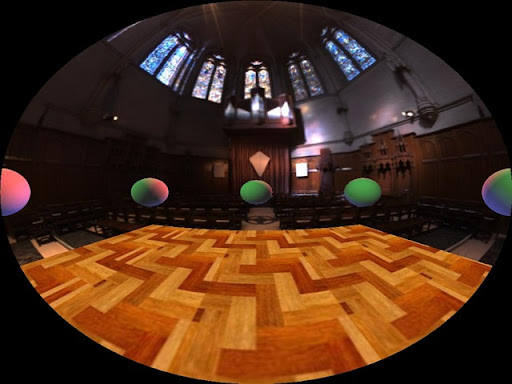
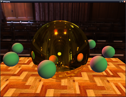
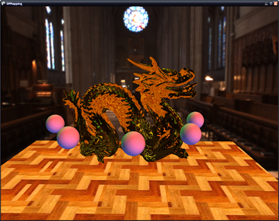
For now, here's a couple of teaser images that we submitted to EGSR. You're looking through a glass bunny's ear. You can see that with regular depth impostors, you are missing a significant amount of data for the teapot lid.

Planar Pinhole Camera Depth Impostor


Non-Pinhole Camera Depth Impostor

Wednesday, July 30, 2008

Other recent blog posts

There are a few posts that I have seen other blogs/sites that I think are interesting, and would like to share with anyone who reads my blog.

Andy Patrick has a series of useful "efficient development" posts regarding speeding up and making game development easier. Check it out:

Efficient Development, Part I
Efficient Development, Part II
Efficient Development, Part III
Efficient Development, Part IV


Next up there were a couple of articles on Gamasutra related to 2D fluid dynamics that are also pretty interesting.

Fluid Dynamics, Part I
Fluid Dynamics, Part II


Christer Ericson has an interesting post on using cellular automata for path finding. And one of the guys over at XNAInfo already has a working XNA demo implementing the idea.

Path finding with cellular automata
Game of Life on the GPU

Got any interesting links? Post 'em in the comments!

Friday, July 18, 2008

Dual-Paraboloid Variance Shadow Mapping

dp_vsm

Edit: Added the video that I recently made

I have to say, I really like variance shadow mapping. It's such a simple(ingenious) technique to implement, but it provides such nice looking results. I haven't had the need to implement the technique before, but I'm glad I did. Last post we implemented dual-paraboloid shadow mapping. And those of you with a PS 3.0 graphics card were able to have semi-soft shadows with percentage closer filtering. But now when we get rid of the PCF filter, and replace it with variance shadow mapping, we can fit all the code inside the PS 2.0 standard. Anyway, on to the code.

Variance Shadow Mapping Paper + Demo

Building the shadow maps:

Variance shadow mapping is really simple to implement. First thing we need to change is to create either a RG32F or RG16F surface format for our front and rear shadow maps (instead of R32F/R16F). This allows us to store the depth of the pixel in the red channel and the squared depth of the pixel in the green channel. So our new pixel shader for building the depth/shadow maps is this:

return float4(z, z * z, 0, 0, 1);

Blurring the shadow maps:

Variance shadow mapping improves upon standard shadow mapping by storing a distribution of depths at each pixel (z * z, and z) instead of the single depth (as with standard shadow mapping). And because it stores a distribution of depth, we can blur the shadow maps. This would produce some funky/incorrect results if we were just doing standard shadow mapping with a PCF filter.

So, after we have created our depth maps, we will blur them with a separable Gaussian blur. This will perform two passes on each shadow map; the first will perform a horizontal blur and the second will perform a vertical blur. There is a wealth of information on the internet on how to do this so I won't explicitly cover this. Here's what our front shadow map looks like after being blurred:

depth_front

Variance shadow mapping:

We build our texture coordinates exactly the same as the previous method of shadow mapping. But the depth comparison is a little different. You can refer to the VSM paper for an in-depth discussion, but here is the gist of it. Since we filtered our shadow maps with a Gaussian blur, we need to recover the moments over that filter region. The moments are simple the depth and squared depth we stored in the texture. From these we can build the mean depth and the variance at the pixel. And as such the variance can be interpreted as a quantitative measure of the width of a distribution (Donelly/Lauritzen). This measure places a bound on the distribution and can be represented by Chebychev's inequality.

float depth;
float mydepth;
float2 moments;
if(alpha >= 0.5f)
{
moments = tex2D(ShadowFrontS, P0.xy).xy;
depth = moments.x;
mydepth = P0.z;
}
else
{
moments = tex2D(ShadowBackS, P1.xy).xy;
depth = moments.x;
mydepth = P1.z;
}

float lit_factor = (mydepth <= moments[0]);

float E_x2 = moments.y;
float Ex_2 = moments.x * moments.x;
float variance = min(max(E_x2 - Ex_2, 0.0) + SHADOW_EPSILON, 1.0);
float m_d = (moments.x - mydepth);
float p = variance / (variance + m_d * m_d); //Chebychev's inequality

texColor.xyz *= max(lit_factor, p + .2f); //lighten the shadow just a bit (with the + .2f)

return texColor;

5x5 Guassian Blur

dp_vsm2


9x9 Guassian Blur

dp_vsm3

And there you go. Nice looking dual-paraboloid soft shadows thanks to variance shadow mapping.

As before, your card needs to support either RG16F or RG32F formats (sorry again Charles :) ). You can refer to the VSM paper and demo on how to map 2 floats to a single ARGB32 pixel if your card doesn't support the floating point surface formats.


Thursday, July 17, 2008

Dual-Paraboloid Shadow Maps

DPShadow2

Last time I introduced using dual-paraboloid environment mapping for reflections. Well now we're going to apply the same process to shadows. So if you haven't looked at my previous post, read it over before going on.

Creating the depth/shadow maps is exactly the same as when we created the reflection maps with one exception. Instead of outputting color in the pixel shader, we output the depth of the 3d pixel, like so:

return depth.x / depth.y;

Where depth.x is the depth of the pixel and depth.y is the w component. And here is the resulting depth/shadow map for the front hemisphere.

depth_f

Now, to map the shadows the process is also very similar to how we generated the reflections. We follow a similar process in the pixel shader:

  • Generate the texture coordinates for the front and rear paraboloids
  • Generate the depth of the pixel
  • Test to see if the pixel is in shadow

We generate the texture coordinates exactly as when we generated the reflection texture coordinates. To generate the depth of the pixel we take the length of the vector from the vertex to the origin of the paraboloid (0, 0, 0) and divide by the light attenuation. Also to check which hemisphere we are in, we calculate an alpha that is the Z value of the transformed vertex and offset by .5f;

float L = length(pos);
float3 P0 = pos / L;

float alpha = .5f + pos.z / LightAttenuation;
//generate texture coords for the front hemisphere
P0.z = P0.z + 1;
P0.x = P0.x / P0.z;
P0.y = P0.y / P0.z;
P0.z = L / LightAttenuation;

P0.x = .5f * P0.x + .5f;
P0.y = -.5f * P0.y + .5f;

float3 P1 = pos / L;
//generate texture coords for the rear hemisphere
P1.z = 1 - P1.z;
P1.x = P1.x / P1.z;
P1.y = P1.y / P1.z;
P1.z = L / LightAttenuation;

P1.x = .5f * P1.x + .5f;
P1.y = -.5f * P1.y + .5f;

Now that we have generated our texture coordinates we need to test the depth of the pixel against the depth in the shadow map. To do this we index either the front or rear shadow map with the texture coordinates we generated to get the depth and compare this to our depth. If the depth is less than our depth, then the pixel is in shadow.

float depth;
float mydepth;
if(alpha >= 0.5f)
{
depth = tex2D(ShadowFrontS, P0.xy).x;
mydepth = P0.z;
}
else
{
depth = tex2D(ShadowBackS, P1.xy).x;
mydepth = P1.z;
}

//lighten the shadow just a bit so it isn't completely black
if((depth + SHADOW_EPSILON) < mydepth)
texColor.xyz *= 0.3f;

return texColor;

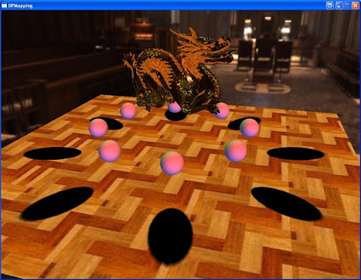
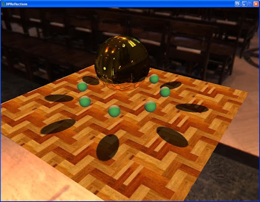
DPShadow

And that's it. Now we have dual-paraboloid shadow mapping. If you have a pixel shader 3.0 graphics card, then the shadow also has a percentage closer filter applied to it. You also may notice seams in the shadows. This is because the splitting plane of the paraboloids is the x-axis (since the paraboloids look down the +/- z-axis). This is one of the problems of using paraboloid mapping for shadows. One has to be careful where they place the split plane to avoid this situation. Pixels that are in the center of either hemisphere suffer little distortion. But this is just a tutorial so I didn't worry too much about it.

Also you're graphics card must be able to support R32F or R16F surface formats to run the demo out of the box (sorry Charles ;) ). Otherwise, you must use the ARGB32 format and pack the depth values in all 4 channels. Here is some code to pack/unpack to/from an ARGB32 surface format. You pass the depth value to the pack method when you render to the shadow maps, and you pass the float4 color to the unpack method when you fetch from the shadow maps. I decided not to implement this so the code wouldn't become complicated by something that doesn't add to the tutorial.

//pack the depth in a 32-bit rgba color
float4 mapDepthToARGB32(const float value)
{
const float4 bitSh = float4(256.0 * 256.0 * 256.0, 256.0 * 256.0, 256.0, 1.0);
const float4 mask = float4(0.0, 1.0 / 256.0, 1.0 / 256.0, 1.0 / 256.0);
float4 res = frac(value * bitSh);
res -= res.xxyz * mask;
return res;
}

//unpack the depth from a 32-bit rgba color
float getDepthFromARGB32(const float4 value)
{
const float4 bitSh = float4(1.0 / (256.0 * 256.0 * 256.0), 1.0 / (256.0 * 256.0), 1.0 / 256.0, 1.0);
return(dot(value, bitSh));
}

Next time I'll introduce using variance shadow mapping with our dual-paraboloid shadow mapping to give nice soft shadows that we can still use with pixel shader 2.0 cards.


Wednesday, July 16, 2008

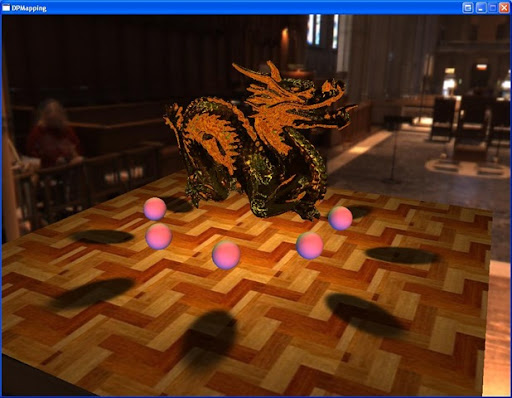
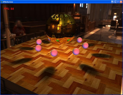
Dual-Paraboloid Reflections

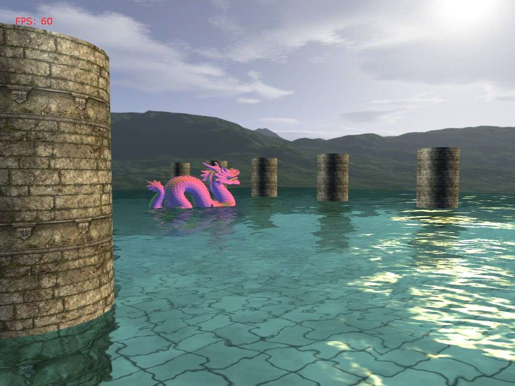
dragon

I recently had to investigate dual-paraboloid reflections at work for an unnamed console. What are these you ask? Great question! :) Lets start with some background.

The standard way of calculating reflections is to use an environment map, more specifically a cube map. In my last tutorial on reflections, this basic type of reflection mapping was used to compare against billboard impostor reflections. Now, cubemaps are great for static scenes, and are relatively low cost to perform a texture fetch on in a shader. However if you have a dynamic scene you have to update all 6 sides of the cubemap (this is not technically true, aggressive culling and other optimizations can guarantee at most 5 sides). Holy crap, now we have to render our scene 6 times!

This is where dual-paraboloid reflections come in. They are a view-independent method of rendering reflections just like cubemaps. Except you only have to update 2 textures, not 6! The downside is that you are going to lose quality for speed, but unless you have to have high-quality reflections, paraboloid reflections will probably provide sufficient results.

Reference articles:

View-Independent Environment Maps

Shadow Mapping for Hemispherical and Omnidirectional Light Sources

Dual Paraboloid Mapping in the Vertex Shader

In the interest of keeping this post from getting too long, I won't go into great detail on the mathematical process. I suggest you refer to the first and third papers for an in-depth discussion on the details.

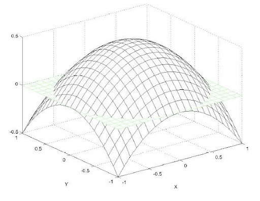
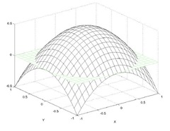
Now lets move on to what exactly paraboloid mapping is. Lets look at what a paraboloid is.
paraboloid

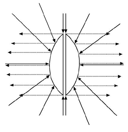
The basic idea is that for any origin O, we can divide the scene into two hemispheres, front and rear. For each of these hemispheres there exists a paraboloid surface that will focus any ray traveling in the direction of O into the direction of the the hemisphere. Here is a 2d picture demonstrating the idea:

paraboloid2d

A brief math overview:

What we need to find is the intersection point where the incident ray intersects the paraboloid surface. To do this we need to know the incident ray and the reflected ray. Now because the paraboloid reflects rays in the same direction, it is easy to compute the reflection vector: it's the forward direction of the hemisphere! So the front hemisphere's reflection vector will always be <0, 0, 1> and the rear hemisphere's reflection vector will always be <0, 0, -1>. Easy! And the incident ray is calculated the same as with environment mapping by reflecting the ray from the pixel position to the eye across the normal of the 3D pixel.

Now all we have to do is find the normal of the intersection which we will use to map our vertices into paraboloid space. To find the normal, we add the incident and reflected vectors and divide the x and y components by the z value.

Generating the Paraboloid maps:

What we are basically going to do is, in the vertex shader, place each vertex ourselves that has been distorted by the paraboloid. First we need to transform the vertex by the view matrix of the paraboloid 'camera'. We don't apply the projection matrix since we're going to place the point ourselves

output.Position = mul(input.Position, WorldViewProj);

Next we need to find the vector from the the vertex to the origin of the paraboloid, which is simply:

float L = length( output.Position.xyz );
output.Position = output.Position / L;

Now we need to find the x and y coordinates of the point where the incident ray intersects the paraboloid surface.

output.Position.z = output.Position.z + 1;
output.Position.x = output.Position.x / output.Position.z;
output.Position.y = output.Position.y / output.Position.z;

Finally we set the z value as the distance from the vertex to the origin of the paraboloid, scaled and biased by the near and far planes of the paraboloid 'camera'.

output.Position.z = (L - NearPlane) / (FarPlane - NearPlane);
output.Position.w = 1;

And the only thing we need to add in the pixel shader is to make sure and clip vertices that are behind the viewpoint using the intrinsic clip() function of HLSL.
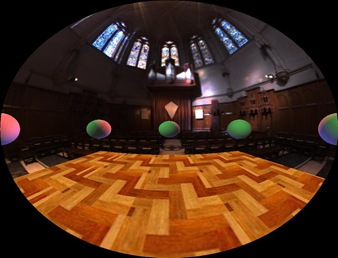
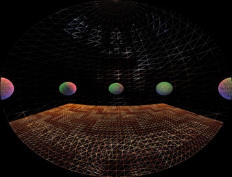
front

frontWF

Reflections with paraboloid maps:

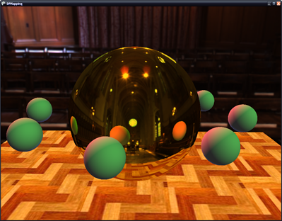
In the reflection pixel shader we will: generate the reflection vector the same way as cube mapping, generate texture coordinates for both the front and rear paraboloids' textures, and blend the samples taken from the textures.

The texture coordinates are generated exactly as how we generated them before in the generation step. We also scale and bias them to correctly index a D3D texture. And then we take a sample from each map and pick the sample with the greater color value:

// calculate the front paraboloid map texture coordinates
float2 front;
front.x = R.x / (R.z + 1);
front.y = R.y / (R.z + 1);
front.x = .5f * front.x + .5f; //bias and scale to correctly sample a d3d texture
front.y = -.5f * front.y + .5f;

// calculate the back paraboloid map texture coordinates
float2 back;
back.x = R.x / (1 - R.z);
back.y = R.y / (1 - R.z);
back.x = .5f * back.x + .5f; //bias and scale to correctly sample a d3d texture
back.y = -.5f * back.y + .5f;

float4 forward = tex2D( FrontTex, front ); // sample the front paraboloid map
float4 backward = tex2D( BackTex, back ); // sample the back paraboloid map

float4 finalColor = max(forward, backward);
ss1

Optimizations:

If you align the paraboloid 'camera' such that it is always facing down the +/- z axis, you don't need to transform the vertices by the view matrix of the camera. You only need to do a simple translation of the vertex by the camera position.

Conclusion:

As you can see, paraboloid maps give pretty good results. The won't give you the quality of cubemaps, but they are faster to update and require less memory. And in the console world, requiring less is almost reason enough to pick this method over cubemaps.

One drawback of paraboloid maps is that the environment geometry has to be sufficiently tessellated or will we will have noticeable artifacts on our reflector. Another drawback is that on spherical objects we will see seems. However with objects that are reasonably complex (such as the Stanford bunny or dragon) and are not simple shapes, the seams will not be as noticeable.

Next time I will present dual-paraboloid mapping for use with real-time omnidirectional shadow mapping of point lights.

Friday, June 20, 2008

Terrain and Atmospheric Scattering Source


I figured I would release my source for the terrain rendering demo. There aren't that many terrain and atmospheric scattering examples on the net, so I figured I might as well post mine for anyone that would like to see it.
It's still a work in progress (that I paused about a year ago), so it's kind of immature. But it is the same code that produced the images I posted awhile back. You'll probably need at least a 6 series Nvidia graphics card (or ATi equivalent). For the terrain, the demo uses a simple quad tree with frustum culling, so it's not the greatest performer for anything above 512x512 heigtmaps. Also, it is in Managed DirectX, but it shouldn't be too hard to port to XNA.


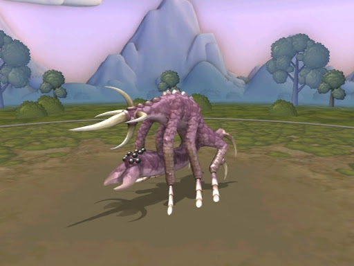
Anyway, enough of that. If you didn't know, the Creature Creator for Spore has been released, and it's an absolute blast to mess around with. The possibilities on what you can create are pretty much endless. Here's a couple that I made:
CRE_spider-0685c592_sml
CRE_Graptilosaurus-0685c593_sml

Tuesday, June 3, 2008

Post Process Framework Sample

dof

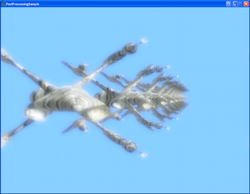
Today I'm posting a post processing framework sample. For those that don't know, post processing is any manipulation of the frame buffer after the scene has been rendered (but usually before the UI), hence the word "post" in the name. This process could be a simple blurring, or it could be a motion blur or depth of field technique. But what if you have many post processes? For instance, maybe we have bloom, motion blur, heat haze, depth of field, and other post processes that we need to apply after we render our scene. Connecting all these post processes together can get a little hairy, and that's what this sample helps us do.

So lets talk about how we're going to structure our framework. At the very bottom of the hierarchy, we have a PostProcessComponent (component from here on out). And what this class represents, is a single atomic process, that is, it cannot be broken up into smaller pieces/objects. Each component has an input and an output in the form of textures. A component is also able to update the backbuffer. It is the simplest object in the hierarchy and is combined with other components to form a PostProcessEffect (effect from here on out).

An effect contains a chain of components to implement a single post process such as bloom or motion blur. An effect also handles output from one component to input to another. In this way the components can be independent of one another, and the effect handles linking all the components that it owns. Because of this, each component is very simple. Also, like components, effects have inputs and outputs in the form of textures. Effects can also be enabled/disabled dynamically at runtime.

Next we have the PostProcessManager(aka manager). The manager is comprised of a chain of effects, and it handles linking the output of one effect to the input of the next effect. And just like with components, this enables each effect to be independent of the next. The manager also takes care of linking the backbuffer and depth buffer to components that need it.

Because each component is not dependent on other components, each one is very simple in its implementation. This not only helps in understanding the code, but also in robustness and tracking down any possible errors in a component. Another nice feature about this framework is that you do not need to create a separate class deriving from PostProcessEffect for each effect. In this way, you can dynamically create your effects at run time. Most of the "magic" occurs in the LoadContent() function inside PostProcessManager. So lets have a look at it:

public void LoadContent()
{
#region Create common textures to be used by the effects
PresentationParameters pp = mGraphicsDevice.PresentationParameters;
int width = pp.BackBufferWidth;
int height = pp.BackBufferHeight;

SurfaceFormat format = pp.BackBufferFormat;

resolveTexture = new ResolveTexture2D(mGraphicsDevice, width, height, 1, format);
#endregion

int
i = 0;
foreach (PostProcessEffect effect in effects)
{
effect.LoadContent();

int j = 0;
//if a component requires a backbuffer, add their function to the event handler
foreach (PostProcessComponent component in effect.Components)
{
//if the component updates/modifies the "scene texture"
//find all the components who need an up to date scene texture
if (component.UpdatesSceneTexture)
{
int k = 0;
foreach (PostProcessEffect e in effects)
{
int l = 0;
foreach (PostProcessComponent c in e.Components)
{
//skip previous components and ourself
if (k < i)
{
continue;
}
else if (k == i && l <= j)
{
l++;
continue;
}
else if (c.RequiresSceneTexture)
{
component.OnUpdateSceneTexture += new UpdateSceneTextureEventHandler(c.UpdateSceneTexture);
}

l++;
}

k++;
}
}

//add the compontent's UpdateBackBuffer method to the event handler
if (component.RequiresBackbuffer
(effect == effects[0] && component == effect.Components[0]))
OnBackBufferResolve += new BackBufferResolveEventHandler(component.UpdateBackbuffer);

if (component.RequiresDepthBuffer)
OnDepthBufferResolve += new DepthBufferResolveEventHandler(component.UpdateDepthBuffer);

j++;
} //components foreach

i++;
} //effects foreach

if (effects.Count > 0)
{
//ensure the last component renders to the backbuffer
effects[effects.Count - 1].IsFinal = true;

if (OnDepthBufferResolve != null)
{
depthBuffer = new BuildZBufferComponent(mContent, mGraphicsDevice);
depthBuffer.Camera = camera;
depthBuffer.Models = models;
depthBuffer.LoadContent();
}
}
}

Here we first setup the resolve texture that will resolve the backbuffer every frame. Then we search through the components, looking for ones that update the backbuffer(scene texture). If a component does this, then we need to find all the components after it that need the most recent version of the backbuffer and assign its update function to the OnUpdateSceneTexture event. Next, we search through all the effects, looking for components that need the backbuffer and depth buffer and attach its backbuffer update function to the OnBackBufferResolve and OnDepthBufferResolve events.

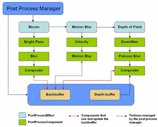
Below is what a sample post process effect chain could look like:

PostProcessDiagram

Here we have three post process effects: bloom, motion blur, and depth of field. Each contains its own components that perform operations on the texture given to it. Some components need to blend with the backbuffer, and therefore need to update the backbuffer in turn so that other components are able to have the most recent copy of the backbuffer (components linked with red lines).

Here is an example of how we could setup the above effect chain:

PostProcessEffect bloom = new PostProcessEffect(Content, Game.GraphicsDevice);
bloom.AddComponent(new BrightPassComponent(Content, Game.GraphicsDevice));
bloom.AddComponent(new GaussBlurComponent(Content, Game.GraphicsDevice));
bloom.AddComponent(new BloomCompositeComponent(Content, Game.GraphicsDevice));

PostProcessEffect motionblur = new PostProcessEffect(Content, Game.GraphicsDevice);
motionblur.AddComponent(new MotionVelocityComponent(Content, Game.GraphicsDevice));
motionblur.AddComponent(new MotionBlurHighComponent(Content, Game.GraphicsDevice));

PostProcessEffect depthOfField = new PostProcessEffect(Content, Game.GraphicsDevice);
depthOfField.AddComponent(new DownFilterComponent(Content, Game.GraphicsDevice));
depthOfField.AddComponent(new PoissonBlurComponent(Content, Game.GraphicsDevice));
depthOfField.AddComponent(new DepthOfFieldComponent(Content, Game.GraphicsDevice));

postManager.AddEffect(bloom);
postManager.AddEffect(motionblur);
postManager.AddEffect(depthOfField);

In the sample, I have included 3 post processes: bloom, depth of field, and a distortion process. I've documented the classes and functions pretty well, so these combined with this write up should be enough to help you understand how everything works. Should you have any questions, just post in the comments.

Homework for the reader:

In this sample, I create a new render target fore every component that needs one. This is bad. In my own implementation that I use for my own projects, I create a render target pool. The render target pool stores and fetches render targets. When a componet requests a render target, the pool will check to see if one of the specified dimensions and format has been stored already. If it has it will return it, if it hasn't it will return a new render target. Now we won't create a new render target for every component. The pool allows us to reuse render targets which helps save gpu memory and increase performance. So if we have 5 effects with 3 components each, we might only create 5 render targets (depending on how many share similar formats and dimensions) instead of 15.


Edit (6/6/2008):Added support for cards that do not support the R32F (Single) SurfaceFormat (hopefully :) ). Removed in-progress auto focusing code in depth-of-field effect.

Edit (6/5/2008): Added some new functionality, namely being able to specify the states and color channel modulation of the spritebatch.


Tuesday, May 20, 2008

New XNA site and other happenings

If you didn't know there's a new version of the creators site up, go check it out.

I've been pretty busy lately. This summer I have an internship with a local game developer, Gabriel Entertainment. They have me working with a Wii dev kit to help bring one of their PC games to the Wii. It's pretty cool stuff.

I'm also working on a remake of the Missile Game 3D flash game in XNA in my free time. I'll be posting the post process manager that I'm using for this project once I port it from XNA 1.0 to 2.0. So stay tuned for this. I'll probably include with this motion blur and depth-of-field post processes.

Saturday, May 3, 2008

Camera Animation, Part II

Camera Animation with a cubic spline:


So last time I lied a little bit about our camera path. I showed this picture:


to describe the path that we wanted. But with linear interpolation, what we really ended up with was something like:


But today, I'll introduce cubic spline interpolation, and this will produce a truly smooth curve. Most of the code is the same, the only thing that has changed is that I have added a cubic option to the build function and have changed the animation to be reliant on time.

Building the natural cubic spline is more math intensive than with linear interpolation, so to start out here's a few links on cubic splines:

//a point on a cubic spline is affected by every other point
//so we need to build the cubic equations for each control point
//by looking at the entire curve. This is what calculateCubicSpline does
Vector3[] looks = new Vector3[mKeyFrames.Count];
Vector3[] positions = new Vector3[mKeyFrames.Count];
Vector3[] ups = new Vector3[mKeyFrames.Count];

for (int i = 0; i < mKeyFrames.Count; i++)
{
looks[i] = mKeyFrames[i].Look;
positions[i] = mKeyFrames[i].Position;
ups[i] = mKeyFrames[i].Up;
}

Cubic[] pos_cubic = calculateCubicSpline(mKeyFrames.Count - 1, positions);
Cubic[] look_cubic = calculateCubicSpline(mKeyFrames.Count - 1, looks);
Cubic[] up_cubic = calculateCubicSpline(mKeyFrames.Count - 1, ups);

for (int i = 0; i < mKeyFrames.Count - 1; i++)
{
for (int j = 0; j < mPathSteps; j++)
{
float k = (float)j / (float)(mPathSteps - 1);

Vector3 center = pos_cubic[i].GetPointOnSpline(k);
Vector3 up = up_cubic[i].GetPointOnSpline(k);
Vector3 look = look_cubic[i].GetPointOnSpline(k);

Vector3 r = Vector3.Cross(up, look);
Vector3 u = Vector3.Cross(look, r * -1f);

Camera cam = new Camera();
cam.SetLens(mFOV, mAspect, mNearZ, mFarZ);
cam.Place(center, look, u);

cam.BuildView();

mCameraPath.Add(cam);
}
}
So the first thing we do is build the cubic polynomials for each control point. And because each point controls the shape of the spline, we have to consider each point when building the polynomials. In this way, it is very different from linear interpolation in that we have to know information about the whole curve to perform a cubic interpolation rather than just the current and next control point as with linear interpolation. You might be thinking that "well Vector3 already contains a SmoothStep function that performs cubic interpolation". And you're right it does, but just interpolating the two points without knowledge of the whole curve still produces segmented(i.e. not smooth) animation. Once we have the polynomials for each control point, we can perform a cubic interpolation by just looking at the current and next control point, in the same fashion that we did with linear interpolation.

This is what the calculateCubicSpline function does, it builds polynomials for each control point, successively building off of the last control point's polynomial. Let's look at it:

Vector3[] gamma = new Vector3[n + 1];
Vector3[] delta = new Vector3[n + 1];
Vector3[] D = new Vector3[n + 1];
int i;
/* We need to solve the equation
* taken from: http://mathworld.wolfram.com/CubicSpline.html
[2 1 ] [D[0]] [3(v[1] - v[0]) ]
: 1 4 1 : :D[1]: :3(v[2] - v[0]) :
: 1 4 1 : : . : = : . :
: ..... : : . : : . :
: 1 4 1: : . : :3(v[n] - v[n-2]):
[ 1 2] [D[n]] [3(v[n] - v[n-1])]

by converting the matrix to upper triangular.
The D[i] are the derivatives at the control points.
*/

//this builds the coefficients of the left matrix
gamma[0] = Vector3.Zero;
gamma[0].X = 1.0f / 2.0f;
gamma[0].Y = 1.0f / 2.0f;
gamma[0].Z = 1.0f / 2.0f;
for (i = 1; i < n; i++)
{
gamma[i] = Vector3.One / ((4 * Vector3.One) - gamma[i - 1]);
}
gamma[n] = Vector3.One / ((2 * Vector3.One) - gamma[n - 1]);

delta[0] = 3 * (v[1] - v[0]) * gamma[0];
for (i = 1; i < n; i++)
{
delta[i] = (3 * (v[i + 1] - v[i - 1]) - delta[i - 1]) * gamma[i];
}
delta[n] = (3 * (v[n] - v[n - 1]) - delta[n - 1]) * gamma[n];

D[n] = delta[n];
for (i = n - 1; i >= 0; i--)
{
D[i] = delta[i] - gamma[i] * D[i + 1];
}

// now compute the coefficients of the cubics
Cubic[] C = new Cubic[n];
for (i = 0; i < n; i++)
{
C[i] = new Cubic(v[i], D[i], 3 * (v[i + 1] - v[i]) - 2 * D[i] - D[i + 1],
2 * (v[i] - v[i + 1]) + D[i] + D[i + 1]);
}
return C;
Once we find the cubic equation for each control point (key frame), we can use GetPointOnSpline() uses the cubic equation to calculate the intermediate point along the cubic spline.

public Vector3 GetPointOnSpline(float s)
{
return (((d * s) + c) * s + b) * s + a;
}
And that's it. Now we have a smooth animation of our camera. There are many more ways to calculate the curve, including: hermite curves, b-splines, bezier curves, catmull-rom splines, NURBS(Nonuniform Rational B-Splines) and others. Microsoft also has a sample on creating a camera path that appears to be using hermite curves. But they hide all the details from you, and it's just more interesting to know the math behind it isn't it ;) ?

Thursday, May 1, 2008

Camera Animation, Part I


Due to the video being such high frequency, the blogger, youtube video compressors always make the video look like crap. Original can be found here:


So today I'll be giving a tutorial/sample on cut-scene animation, more specifically camera animation. This will be a 2 part tutorial, and this one will focus on linear interpolation of camera key frames.

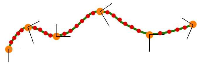
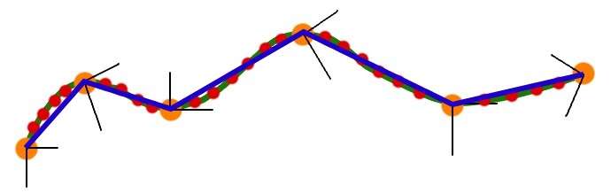
So what are key frames? Key frames are the control points of an animation. They are the main/key points that you specifically define where the camera should be, and everything else in between is interpolated. You can also think of them as an outline of what the animation should look like. Here's a picture to help describe what I'm talking about.

camerapathhn1


Here, the green line is the path we want to follow, the orange dots are our key frames, and the red dots are the intermediate cameras that we want to generate.

So how do we create these intermediate cameras?

for (int i = 0; i < mKeyFrames.Count - 1; i++)
{
for (int j = 0; j < mPathSteps; j++)
{
//We could alternatively use the Vector3.lerp function
//but I wanted to show the math behind performing the linear interpolation

Vector3 diff = mKeyFrames[i + 1].Position - mKeyFrames[i].Position;
diff = Vector3.Multiply(diff, (float)j / (float)(mPathSteps - 1));
Vector3 center = mKeyFrames[i].Position + diff;

diff = mKeyFrames[i + 1].Look - mKeyFrames[i].Look;
diff = Vector3.Multiply(diff, (float)j / (float)(mPathSteps - 1));
Vector3 look = mKeyFrames[i].Look + diff;

diff = (mKeyFrames[i + 1].Up - mKeyFrames[i].Up);
diff = Vector3.Multiply(diff, (float)j / (float)(mPathSteps - 1));
Vector3 up = mKeyFrames[i].Up + diff;

Vector3 r = Vector3.Cross(up, look);
Vector3 u = Vector3.Cross(look, r * -1f);

Camera cam = new Camera();
cam.SetLens(mFOV, mAspect, mNearZ, mFarZ);
cam.Place(center, look, u);

cam.BuildView();

mCameraPath.Add(cam);
}
}
Pretty self explanatory, a basic linear interpolation. XNA is handy in that we can cut out all of that code and just use Vector3.Lerp().

The included demo has a pre defined path that is shown in the video. But you can also create your own path at run-time. Here are the controls:

  • 1 - Default camera view
  • 2 - Play the camera animation
  • 3 - Rewind the camera animation
  • 4 - Pause the camera animation
  • C - Clear the current key frames
  • K - Add the current camera to the key frames list
  • B - Build the camera path from the current key frames
  • O - Save the current key frames to an XML file

When you start the demo, the predefined path is already loaded, all you have to do is hit '2', and it will play. If you want to make your own path first clear the key frames by pressing 'C', and then navigate to where you want to be along your path and press 'K' to add your key frames. Once you're happy with your path, press 'B' to build the camera animation, and then you can play it by pressing '2'. Normally, I would use winForms or a GUI such as neoforce for the controls, but this adds a lot of clutter.

So there's probably one thing that you might notice about the camera animation, and that is that it's not very smooth. Next time I will introduce cubic interpolation to smooth out the animation.