Really cool video I found last night. Uses Particular and Adobe After Effects.
Thursday, August 27, 2009
Thursday, July 30, 2009
Water in Your Browser
Recently I’ve been playing around with O3D. If you don’t know, O3D is Google’s new browser graphics API. It enables you to develop 3d interactive applications that run inside a browser window (and quite easily mind you). In fact it rivals XNA on getting an app up and running quickly.
And on that note, I’ve ported the water sample to O3D (minus the camera animation). Besides a bug I encountered with the sample content converter (and promptly fixed by one of the o3d developers), it was a relatively painless conversion. All that was required was to setup a scene in max, apply materials, export to collada and convert to the o3d format. Setting up the render targets also took minimal effort :). The shaders, for the most part, remained untouched.
Click the picture to have a go!

If you’re interested in the max file or source you can get both here:
Friday, June 19, 2009
Non-photorealistic SSGI
I recently got back from my vacation to the Mediterranean and finally have had time to post this video.
For one of my final projects last semester I implemented a deferred renderer with SSAO and simplified global illumination (SSGI). But I wanted to have a dream-like result, so I over emphasized the color bleeding and used the light accumulation buffer plus emissive color of objects; and lots of blurring. The result looks pretty neat I think, not at all accurate lighting but cool none the less. This one was done in C++/DirectX instead of the usual XNA fare.
Large HD video on youtube
Thursday, April 23, 2009
Volume Rendering Update, DirectX blog
Wow, I can't believe it's almost May already. I also can't believe my last post was back in February! I've had the next installment in the volume rendering series basically done since January. I just have to put some finishing touches on it and write the post. I've just been very busy finishing my last semester, research, searching for a job, and considering graduate school.
I've been working on a deferred renderer and delving into screen space ambient occlusion and global illumination for one of my final projects. I'll probably post some images of the final result when it's done.
Ysaneya has a very interesting post on deferred rendering and instant radiosity.
Also, if you haven't noticed, the DirectX team has a new blog: http://blogs.msdn.com/DirectX/
Wednesday, February 4, 2009
Volume Rendering 201: Optimizations
The discussion on hand this time is optimizing the performance of the volume renderer. I’ll cover a few of these optimizations and provide a rough implementation of one of them.
Cache Efficiency and Memory Access

Picture from Real-time Volume Graphics.
Currently we load our volume data into a linear layout in memory. However, the ray that is cast through the volume is not likely to access neighboring voxels as we traverse it through the volume when the data is in a linear layout. But we can improve the cache efficiency by converting the layout to a block-based manor through swizzling. With the data in a block format, the GPU is more likely to cache neighboring voxels as we walk through the volume, which will lead to an increase in memory performance.
Empty-Space Leaping

In the previous samples we ray-casted against the entire bounding volume of the data set, even if we were just sampling samples with zero alpha along the way. But we can skip these samples all together, and only render parts of the volume that have a non-zero alpha in the transfer function. More on this in a bit.
Occlusion Culling
If we render the volume in a block-based fashion as above, and sort the blocks from front to back, we can use occlusion queries to determine which blocks are completely occluded by blocks in front of them. There are quite a few tutorials on occlusion queries on the net, including this one at ziggyware.
Deferred Shading
We can also boost performance by deferring the shading calculations. Instead shading every voxel during the ray-casting, we can just output the depth and color information into off-screen buffers. Then we render a full-screen quad and use the depth information to calculate normals in screen space and then continue to calculate the shading. Calculating normals this way also has the advantage of being smoother and have less artifacts that computing the gradients of the volume and storing them in a 3D texture. We also save memory this way since we don’t have to save the normals, only the isovalues in the 3D texture.
Image Downscaling
If the data we are rendering is low frequency (e.g. volumetric fog), we can render the volume into an off-screen buffer that is half the size of the window. Then we can up-scale this image during a final pass. This method is also included in the sample.
Implementing Empty-Space Leaping
To implement empty-space leaping we need to subdivide the volume into smaller volumes and we also need to determine if these smaller volumes have an opacity greater than zero. To subdivide the volume we follow an approach very similar to quadtree or octree construction. We start out with an original volume from [0, 0, 0] to [1, 1, 1]. The volume is then recursively subdivided until the volume width is say .1 (so we basically divide the volume along each dimension by 10). Here’s how we do that:
Problems
Now, a problem that this method introduces is overdraw. You can see the effects of this when rotating the camera to view the back of the bear; here the frame rate drops considerably. To remedy this the sub-volumes need to be sorted front to back by their distance to the camera each time the view changes. I’ve left this as an exercise for the reader. The new demo implements empty space leaping and downscaling. And when rendering the teddy bear volume frame rates on my 8800GT are at about 190 FPS. Compare this to the the last demo from 102 at 30 FPS. All at a resolution of 800x600. Pretty good results! Next time I’ll be introducing soft shadows and translucent materials.
References: Real-time Volume Graphics
Cache Efficiency and Memory Access

Picture from Real-time Volume Graphics.
Currently we load our volume data into a linear layout in memory. However, the ray that is cast through the volume is not likely to access neighboring voxels as we traverse it through the volume when the data is in a linear layout. But we can improve the cache efficiency by converting the layout to a block-based manor through swizzling. With the data in a block format, the GPU is more likely to cache neighboring voxels as we walk through the volume, which will lead to an increase in memory performance.
Empty-Space Leaping

In the previous samples we ray-casted against the entire bounding volume of the data set, even if we were just sampling samples with zero alpha along the way. But we can skip these samples all together, and only render parts of the volume that have a non-zero alpha in the transfer function. More on this in a bit.
Occlusion Culling
If we render the volume in a block-based fashion as above, and sort the blocks from front to back, we can use occlusion queries to determine which blocks are completely occluded by blocks in front of them. There are quite a few tutorials on occlusion queries on the net, including this one at ziggyware.
Deferred Shading
We can also boost performance by deferring the shading calculations. Instead shading every voxel during the ray-casting, we can just output the depth and color information into off-screen buffers. Then we render a full-screen quad and use the depth information to calculate normals in screen space and then continue to calculate the shading. Calculating normals this way also has the advantage of being smoother and have less artifacts that computing the gradients of the volume and storing them in a 3D texture. We also save memory this way since we don’t have to save the normals, only the isovalues in the 3D texture.
Image Downscaling
If the data we are rendering is low frequency (e.g. volumetric fog), we can render the volume into an off-screen buffer that is half the size of the window. Then we can up-scale this image during a final pass. This method is also included in the sample.
Implementing Empty-Space Leaping
To implement empty-space leaping we need to subdivide the volume into smaller volumes and we also need to determine if these smaller volumes have an opacity greater than zero. To subdivide the volume we follow an approach very similar to quadtree or octree construction. We start out with an original volume from [0, 0, 0] to [1, 1, 1]. The volume is then recursively subdivided until the volume width is say .1 (so we basically divide the volume along each dimension by 10). Here’s how we do that:
private void RecursiveVolumeBuild(Cube C)
{
     //stop when the current cube is 1/10 of the original volume
     if (C.Width <= 0.1f)
     {
          //add the min/max vertex to the list

          Vector3 min = new Vector3(C.X, C.Y, C.Z);

          Vector3 max = new Vector3(C.X + C.Width, C.Y + C.Height, C.Z + C.Depth);

          Vector3 scale = new Vector3(mWidth, mHeight, mDepth);

          //additively sample the transfer function and check if there are any

         //samples that are greater than zero

         float opacity = SampleVolume3DWithTransfer(min * scale, max * scale);

         if(opacity > 0.0f)

         {

               BoundingBox box = new BoundingBox(min, max);

               //add the corners of the bounding box

               Vector3[] corners = box.GetCorners();

               for (int i = 0; i < 8; i++)

               {

                    VertexPositionColor v;

                    v.Position = corners[i];

                    v.Color = Color.Blue;

                    mVertices.Add(v);

               }

          }

          return;
     }

     float newWidth = C.Width / 2f;
     float newHeight = C.Height / 2f;
     float newDepth = C.Depth / 2f;

     ///  SubGrid        r  c  d
     ///  Front:
     ///  Top-Left    :  0   0   0
     ///  Top-Right   :  0   1   0
     ///  Bottom-Left :  1   0   0
     ///  Bottom-Right:  1   1   0
     ///  Back:
     ///  Top-Left    :  0   0   1
     ///  Top-Right   :  0   1   1
     ///  Bottom-Left :  1   0   1
     ///  Bottom-Right:  1   1   1
     for (float r = 0; r < 2; r++)
     {
          for (float c = 0; c < 2; c++)

          {
                for (float d = 0; d < 2; d++)

                {

                     Cube cube = new Cube(C.Left + c * (newWidth),

                                          C.Top + r * (newHeight),

                                          C.Front + d * (newDepth),

                                          newWidth,

                                          newHeight,

                                          newDepth);

                                          RecursiveVolumeBuild(cube);

                }

          }
     }
}
To determine whether a sub-volume contains any samples that have opacity, we simply loop over the volume and additively sample the transfer function:
private float SampleVolume3DWithTransfer(Vector3 min, Vector3 max)
{
     float result = 0.0f;

     for (int x = (int)min.X; x <= (int)max.X; x++)
     {
          for (int y = (int)min.Y; y <= (int)max.Y; y++)

          {

               for (int z = (int)min.Z; z <= (int)max.Z; z++)

               {

                    //sample the volume to get the iso value

                    //it was stored [0, 1] so we need to scale to [0, 255]

                    int isovalue = (int)(sampleVolume(x, y, z) * 255.0f);

                    //accumulate the opacity from the transfer function

                    result += mTransferFunc[isovalue].W * 255.0f;

               }

          }

     }

     return result;
}
Depending on the transfer function (a lot of zero opacity samples), this method can increase our performance by 50%.
Problems
Now, a problem that this method introduces is overdraw. You can see the effects of this when rotating the camera to view the back of the bear; here the frame rate drops considerably. To remedy this the sub-volumes need to be sorted front to back by their distance to the camera each time the view changes. I’ve left this as an exercise for the reader. The new demo implements empty space leaping and downscaling. And when rendering the teddy bear volume frame rates on my 8800GT are at about 190 FPS. Compare this to the the last demo from 102 at 30 FPS. All at a resolution of 800x600. Pretty good results! Next time I’ll be introducing soft shadows and translucent materials.
References: Real-time Volume Graphics
Tuesday, January 20, 2009
Volume Rendering 102: Transfer Functions
Last time I introduced the concept of volume ray-casting. And to follow that up, today I'll talk about transfer functions and shading.
Mummy (top) and Male (bottom) volumes colored with a transfer function (left) and shaded (right).
A transfer function is used to assign RGB and alpha values for every voxel in the volume. A 1D transfer function maps one RGBA value for every isovalue [0, 255]. Multi-dimensional transfer functions allow multiple RGBA values to be mapped to a single isovalue. These are however out of the scope of this tutorial, so I will just focus on 1D transfer functions.
The transfer function is used to "view" a certain part of the volume. As with the second set of pictures above, there is a skin layer/material and there is a skull layer/material. A transfer function could be designed to just look at the skin, the skull, or both (as is pictured). There are a few different ways of creating transfer functions. One is two manually define the transfer functions by specifying the RGBA values for the isovalues (what we will be doing), and another is through visual controls and widgets. Manually defining the transfer function is a lot like guess work and takes a bit of time, but is the easiest way to get your feet wet. Visually designing transfer functions is the easiest way to get good results quickly as it happens at run-time. But this method is quite complex to implement (at least for a tutorial).
Creating the transfer function:
To create a transfer function, we want to define the RGBA values for certain isovalues (control points or control knots) and then interpolate between these values to produce a smooth transition between layers/materials. Our transfer function will result in a 1D texture with a width of 256.
First we have the TransferControlPoint class. This class takes an RGB color or alpha value for a specific isovalue.

So we have defined a range of color for the skin and a longer range of color for the skull/bone.
But how do we interpolate between the control points? We will fit a cubic spline to the control points to produce a nice smooth interpolation between the knots. For a more in-depth discussion on cubic splines refer to my camera animation tutorial.
Here is a simple graph representation of the spline that is fit to the control points.

Using the transfer function:
So how do we put this transfer function to use? First we set it to a 1D texture and upload it to the graphics card. Then in the shader, we simply take the isovalue sampled from the 3d volume texture and use that to index the transfer function texture.
Calculating Gradients:
The method we will use to calculate the gradients is the central differences scheme. This takes the last and next samples of the current sample to calculate the gradient/normal. This can be performed at run-time in the shader, but as it requires 6 extra texture fetches from the 3D texture, it is quite slow. So we will calculate the gradients and place them in the RGB components of our volume texture and move the isovalue to the alpha channel. This way we only need one volume texture for the data set instead of two: one for the gradients and one for the isovalues.
Calculating the gradients is pretty simple. We just loop through all the samples and find the difference between the next and previous sample to calculate the gradients:
Now that we have the gradients we just fill the xyz components of the 3D volume texture and put the isovalue in the alpha channel:
A teapot with just transfer function:

The teapot with transfer function and shaded:


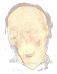
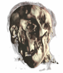
Now a CT scan of a male head. Just transfer function:

Now with shading:


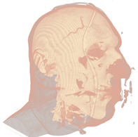
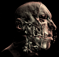
And a mummy:


*The CT Male data set was converted from PVM format to RAW format with the V3 library. The original data set can be found here: http://www9.informatik.uni-erlangen.de/External/vollib/


Mummy (top) and Male (bottom) volumes colored with a transfer function (left) and shaded (right).
A transfer function is used to assign RGB and alpha values for every voxel in the volume. A 1D transfer function maps one RGBA value for every isovalue [0, 255]. Multi-dimensional transfer functions allow multiple RGBA values to be mapped to a single isovalue. These are however out of the scope of this tutorial, so I will just focus on 1D transfer functions.
The transfer function is used to "view" a certain part of the volume. As with the second set of pictures above, there is a skin layer/material and there is a skull layer/material. A transfer function could be designed to just look at the skin, the skull, or both (as is pictured). There are a few different ways of creating transfer functions. One is two manually define the transfer functions by specifying the RGBA values for the isovalues (what we will be doing), and another is through visual controls and widgets. Manually defining the transfer function is a lot like guess work and takes a bit of time, but is the easiest way to get your feet wet. Visually designing transfer functions is the easiest way to get good results quickly as it happens at run-time. But this method is quite complex to implement (at least for a tutorial).
Creating the transfer function:
To create a transfer function, we want to define the RGBA values for certain isovalues (control points or control knots) and then interpolate between these values to produce a smooth transition between layers/materials. Our transfer function will result in a 1D texture with a width of 256.
First we have the TransferControlPoint class. This class takes an RGB color or alpha value for a specific isovalue.
public class TransferControlPoint{
    public Vector4 Color;
    public int IsoValue;

    /// <summary>
    /// Constructor for color control points.
    /// Takes rgb color components that specify the color at the supplied isovalue.
    /// </summary>
    /// <param name="x"></param>
    /// <param name="y"></param>
    /// <param name="z"></param>
    /// <param name="isovalue"></param>
    public TransferControlPoint(float r, float g, float b, int isovalue)
    {
        Color.X = r;
        Color.Y = g;
        Color.Z = b;
        Color.W = 1.0f;
        IsoValue = isovalue;
    }

    /// <summary>
    /// Constructor for alpha control points.
    /// Takes an alpha that specifies the aplpha at the supplied isovalue.
    /// </summary>
    /// <param name="alpha"></param>
    /// <param name="isovalue"></param>
    public TransferControlPoint(float alpha, int isovalue)
    {
        Color.X = 0.0f;
        Color.Y = 0.0f;
        Color.Z = 0.0f;
        Color.W = alpha;
        IsoValue = isovalue;
    }
}
This class will represent the control points that we will interpolate. I've added two lists to the Volume class, mAlphaKnots and mColorKnots. These will be the list of transfer control points that we will setup and interpolate to produce the transfer function. To produce the result for the Male dataset above, here are the transfer control points that we will define:
mesh.ColorKnots = new List<TransferControlPoint> {
                        new TransferControlPoint(.91f, .7f, .61f, 0),
                        new TransferControlPoint(.91f, .7f, .61f, 80),
                        new TransferControlPoint(1.0f, 1.0f, .85f, 82),
                        new TransferControlPoint(1.0f, 1.0f, .85f, 256)
                        };

mesh.AlphaKnots = new List<TransferControlPoint> {
                        new TransferControlPoint(0.0f, 0),
                        new TransferControlPoint(0.0f, 40),
                        new TransferControlPoint(0.2f, 60),
                        new TransferControlPoint(0.05f, 63),
                        new TransferControlPoint(0.0f, 80),
                        new TransferControlPoint(0.9f, 82),
                        new TransferControlPoint(1f, 256)
                        };
You need to specify at least two control points at isovalues 0 and 256 for both alpha and color. Also the control points need to be ordered (low to high) by the isovalue. So the first entry in the list should always be the RGB/alpha value for the zero isovalue, and the last entry should always be the RGB/alpha value for the 256 isovalue. The above list of control points produce the following transfer function after interpolation:
So we have defined a range of color for the skin and a longer range of color for the skull/bone.
But how do we interpolate between the control points? We will fit a cubic spline to the control points to produce a nice smooth interpolation between the knots. For a more in-depth discussion on cubic splines refer to my camera animation tutorial.
Here is a simple graph representation of the spline that is fit to the control points.

Using the transfer function:
So how do we put this transfer function to use? First we set it to a 1D texture and upload it to the graphics card. Then in the shader, we simply take the isovalue sampled from the 3d volume texture and use that to index the transfer function texture.
value = tex3Dlod(VolumeS, pos);

src = tex1Dlod(TransferS, value.a);
Now we have the color and opacity of the current sample. Next, we have to shade it. While this is simply diffuse shading I will go over how to calculate gradients (aka normals) for the 3D volume.
Calculating Gradients:
The method we will use to calculate the gradients is the central differences scheme. This takes the last and next samples of the current sample to calculate the gradient/normal. This can be performed at run-time in the shader, but as it requires 6 extra texture fetches from the 3D texture, it is quite slow. So we will calculate the gradients and place them in the RGB components of our volume texture and move the isovalue to the alpha channel. This way we only need one volume texture for the data set instead of two: one for the gradients and one for the isovalues.
Calculating the gradients is pretty simple. We just loop through all the samples and find the difference between the next and previous sample to calculate the gradients:
/// <summary>
/// Generates gradients using a central differences scheme./// </summary>
/// <param name="sampleSize">The size/radius of the sample to take.</param>private void generateGradients(int sampleSize)
{
    int n = sampleSize;
    Vector3 normal = Vector3.Zero;
    Vector3 s1, s2;

    int index = 0;
    for (int z = 0; z < mDepth; z++)
    {
        for (int y = 0; y < mHeight; y++)
        {
            for (int x = 0; x < mWidth; x++)
            {
                s1.X = sampleVolume(x - n, y, z);
                s2.X = sampleVolume(x + n, y, z);
                s1.Y = sampleVolume(x, y - n, z);
                s2.Y = sampleVolume(x, y + n, z);
                s1.Z = sampleVolume(x, y, z - n);
                s2.Z = sampleVolume(x, y, z + n);

                mGradients[index++] = Vector3.Normalize(s2 - s1);
                if (float.IsNaN(mGradients[index - 1].X))
                    mGradients[index - 1] = Vector3.Zero;
            }
        }
    }
}
Next we will filter the gradients to smooth them out and prevent any high irregularities. We achieve this by a simple NxNxN cube filter. A cube filter simply averages the surrounding N^3 - 1 samples. Here's the code for the gradient filtering:
/// <summary>
/// Applies an NxNxN filter to the gradients./// Should be an odd number of samples. 3 used by default./// </summary>
/// <param name="n"></param>private void filterNxNxN(int n)
{
    int index = 0;
    for (int z = 0; z < mDepth; z++)
    {
        for (int y = 0; y < mHeight; y++)
        {
            for (int x = 0; x < mWidth; x++)
            {
                mGradients[index++] = sampleNxNxN(x, y, z, n);
            }
        }
    }
}

/// <summary>
/// Samples the sub-volume graident volume and returns the average./// Should be an odd number of samples./// </summary>
/// <param name="x"></param>
/// <param name="y"></param>
/// <param name="z"></param>
/// <param name="n"></param>
/// <returns></returns>private Vector3 sampleNxNxN(int x, int y, int z, int n)
{
    n = (n - 1) / 2;

    Vector3 average = Vector3.Zero;
    int num = 0;

    for (int k = z - n; k <= z + n; k++)
    {
        for (int j = y - n; j <= y + n; j++)
        {
            for (int i = x - n; i <= x + n; i++)
            {
                if (isInBounds(i, j, k))
                {
                    average += sampleGradients(i, j, k);
                    num++;
                }
            }
        }
    }

    average /= (float)num;
    if (average.X != 0.0f && average.Y != 0.0f && average.Z != 0.0f)
        average.Normalize();

    return average;
}
This is a really simple and slow way of filtering the gradients. A better way is to use a seperable 3D Gaussian kernal to filter the gradients.
Now that we have the gradients we just fill the xyz components of the 3D volume texture and put the isovalue in the alpha channel:
//transform the data to HalfVector4HalfVector4[] gradients = new HalfVector4[mGradients.Length];
for (int i = 0; i < mGradients.Length; i++)
{
    gradients[i] = new HalfVector4(mGradients[i].X, mGradients[i].Y, mGradients[i].Z, mScalars[i].ToVector4().W);
}

mVolume.SetData<HalfVector4>(gradients);
mEffect.Parameters["Volume"].SetValue(mVolume);
And that's pretty much it. Creating a good transfer function can take a little time, but this simple 1D transfer function can still produce pretty good results. Here's a few captures of what this demo can produce:
A teapot with just transfer function:

The teapot with transfer function and shaded:


Now a CT scan of a male head. Just transfer function:

Now with shading:


And a mummy:


*The CT Male data set was converted from PVM format to RAW format with the V3 library. The original data set can be found here: http://www9.informatik.uni-erlangen.de/External/vollib/
Thursday, January 15, 2009
Volume Rendering 101


Pictures above from: http://www.cs.utah.edu/~jmk/simian/


There is quite a bit of documentation and papers on volume rendering. But there aren't many good tutorials on the subject (that I have seen). So this tutorial will try to teach the basics of volume rendering, more specifically volume ray-casting (or volume ray marching).
What is volume ray-casting you ask? You didn't? Oh, well I'll tell you anyway. Volume rendering is a method for directly displaying a 3D scalar field without first fitting an intermediate representation to the data, such as triangles. How do we render a volume without geometry? There are two traditional ways of rendering a volume: slice-based rendering and volume ray-casting. This tutorial will be focusing on volume ray-casting. There are many advantages over slice-based rendering that ray-casting provides; such as empty space skipping, projection independence, simple to implement, and single pass.
Volume ray-casting (also called ray marching) is exactly how it sounds. [edit: volume ray-casting is not the same as ray-casting ala Doom or Nick's tutorials] Rays are cast through the volume and is sample along equally spaced intervals. As the ray is marched through the volume scalar values are mapped to optical properties through the
use of a transfer function which results in an RGBA color value that includes the corresponding emission and absorption coefficients for the current sample point. This color is then composited by using front-to-back or back-to-front alpha blending.
This tutorial will focus specifically on how to intersect a ray with the volume and march it through the volume. In another tutorial I will focus on transfer functions and shading.
First we need to know how to read in the data. The data is simply scalar values (usually integers or floats) stored as slices [x, y, z], where x = width, y = height, and z = depth. Each slice is x units wide and y units high, and the total number of slices is equal to z. A common format for the data is to be stored in 8-bit or 16-bit RAW format. Once we have the data, we need to load it into a volume texture. Here's how we do the whole process:
//create the scalar volume texturemVolume = new Texture3D(Game.GraphicsDevice, mWidth, mHeight, mDepth, 0,
                        TextureUsage.Linear, SurfaceFormat.Single);

private void loadRAWFile8(FileStream file)
{
    BinaryReader reader = new BinaryReader(file);

    byte[] buffer = new byte[mWidth * mHeight * mDepth];
    int size = sizeof(byte);

    reader.Read(buffer, 0, size * buffer.Length);

    reader.Close();

    //scale the scalar values to [0, 1]
    mScalars = new float[buffer.Length];
    for (int i = 0; i < buffer.Length; i++)
    {
        mScalars[i] = (float)buffer[i] / byte.MaxValue;
    }

    mVolume.SetData(mScalars);
    mEffect.Parameters["Volume"].SetValue(mVolume);
}
In order to render this texture we fit a bounding box or cube, that is from [0,0,0] to [1,1,1] to the volume. And we render the cube and sample the volume texture to render the volume. But we also need a way to find the ray that starts at the eye/camera and intersects the cube.

We could always calculate the intersection of the ray from the eye to the current pixel position with the cube by performing a ray-cube intersection in the shader. But a better and faster way to do this is to render the positions of the front and back facing triangles of the cube to textures. This easily gives us the starting and end positions of the ray, and in the shader we simply sample the textures to find the sampling ray.
Here's what the textures look like (Front, Back, Ray Direction):


And here's the code to render the front and back positions:
//draw front faces
//draw the pixel positions to the textureGame.GraphicsDevice.SetRenderTarget(0, mFront);
Game.GraphicsDevice.Clear(Color.Black);

base.DrawCustomEffect();

Game.GraphicsDevice.SetRenderTarget(0, null);
//draw back faces
//draw the pixel positions to the textureGame.GraphicsDevice.SetRenderTarget(0, mBack);
Game.GraphicsDevice.Clear(Color.Black);
Game.GraphicsDevice.RenderState.CullMode = CullMode.CullCounterClockwiseFace;

base.DrawCustomEffect();

Game.GraphicsDevice.SetRenderTarget(0, null);
Game.GraphicsDevice.RenderState.CullMode = CullMode.CullClockwiseFace;
Now, to perform the actual ray-casting of the volume, we render the front faces of the cube. In the shader we sample the front and back position textures to find the direction (back - front) and starting position (front) of the ray that will sample the volume. The volume is then iteratively sampled by advancing the current sampling position along the ray at equidistant steps. And we use front-to-back compositing to accumulate the pixel color.
float4 RayCastSimplePS(VertexShaderOutput input) : COLOR0{
    //calculate projective texture coordinates
    //used to project the front and back position textures onto the cube
    float2 texC = input.pos.xy /= input.pos.w;
    texC.x =  0.5f*texC.x + 0.5f;
    texC.y = -0.5f*texC.y + 0.5f;

    float3 front = tex2D(FrontS, texC).xyz;
    float3 back = tex2D(BackS, texC).xyz;

    float3 dir = normalize(back - front);
    float4 pos = float4(front, 0);

    float4 dst = float4(0, 0, 0, 0);
    float4 src = 0;

    float value = 0;

    float3 Step = dir * StepSize;

    for(int i = 0; i < Iterations; i++)
    {
        pos.w = 0;
        value = tex3Dlod(VolumeS, pos).r;

        src = (float4)value;
        src.a *= .5f; //reduce the alpha to have a more transparent result

        //Front to back blending
        // dst.rgb = dst.rgb + (1 - dst.a) * src.a * src.rgb
        // dst.a   = dst.a   + (1 - dst.a) * src.a
        src.rgb *= src.a;
        dst = (1.0f - dst.a)*src + dst;

        //break from the loop when alpha gets high enough
        if(dst.a >= .95f)
            break;

        //advance the current position
        pos.xyz += Step;

        //break if the position is greater than <1, 1, 1>
        if(pos.x > 1.0f  pos.y > 1.0f  pos.z > 1.0f)
            break;
    }

    return dst;
}
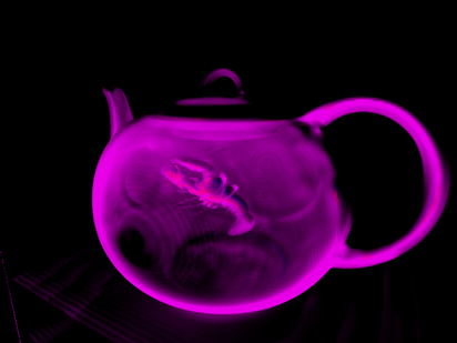
And here's the result when sampling a foot, teapot with a lobster inside, engine, bonsai tree, ct scan of an aneurysm, skull, and a teddy bear:


So, not very colorful but pretty cool. When we get into transfer functions we will start shading the volumes. The volumes used here can be found at volvis.org
Notes:
Refer to the scene setup region in VolumeRayCasting.cs, Volume.cs, and RayCasting.fx for relevant implementation details.
Also, a Shader Model 3.0 card (Nvidia 6600GT or higher) is needed to run the sample.
Subscribe to:
Posts (Atom)