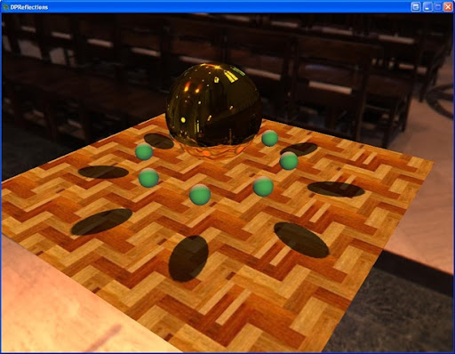
Last time I introduced using dual-paraboloid environment mapping for reflections. Well now we're going to apply the same process to shadows. So if you haven't looked at my previous post, read it over before going on.
Creating the depth/shadow maps is exactly the same as when we created the reflection maps with one exception. Instead of outputting color in the pixel shader, we output the depth of the 3d pixel, like so:
return depth.x / depth.y;
Where depth.x is the depth of the pixel and depth.y is the w component. And here is the resulting depth/shadow map for the front hemisphere.

Now, to map the shadows the process is also very similar to how we generated the reflections. We follow a similar process in the pixel shader:
- Generate the texture coordinates for the front and rear paraboloids
- Generate the depth of the pixel
- Test to see if the pixel is in shadow
We generate the texture coordinates exactly as when we generated the reflection texture coordinates. To generate the depth of the pixel we take the length of the vector from the vertex to the origin of the paraboloid (0, 0, 0) and divide by the light attenuation. Also to check which hemisphere we are in, we calculate an alpha that is the Z value of the transformed vertex and offset by .5f;
float L = length(pos);
float3 P0 = pos / L;

float alpha = .5f + pos.z / LightAttenuation;
//generate texture coords for the front hemisphere
P0.z = P0.z + 1;
P0.x = P0.x / P0.z;
P0.y = P0.y / P0.z;
P0.z = L / LightAttenuation;

P0.x = .5f * P0.x + .5f;
P0.y = -.5f * P0.y + .5f;

float3 P1 = pos / L;
//generate texture coords for the rear hemisphere
P1.z = 1 - P1.z;
P1.x = P1.x / P1.z;
P1.y = P1.y / P1.z;
P1.z = L / LightAttenuation;

P1.x = .5f * P1.x + .5f;
P1.y = -.5f * P1.y + .5f;
Now that we have generated our texture coordinates we need to test the depth of the pixel against the depth in the shadow map. To do this we index either the front or rear shadow map with the texture coordinates we generated to get the depth and compare this to our depth. If the depth is less than our depth, then the pixel is in shadow.
float depth;
float mydepth;
if(alpha >= 0.5f)
{
    depth = tex2D(ShadowFrontS, P0.xy).x;
    mydepth = P0.z;
}
else
{
    depth = tex2D(ShadowBackS, P1.xy).x;
    mydepth = P1.z;
}

//lighten the shadow just a bit so it isn't completely black
if((depth + SHADOW_EPSILON) < mydepth)
    texColor.xyz *= 0.3f;

return texColor;
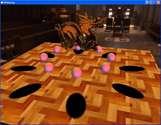
And that's it. Now we have dual-paraboloid shadow mapping. If you have a pixel shader 3.0 graphics card, then the shadow also has a percentage closer filter applied to it. You also may notice seams in the shadows. This is because the splitting plane of the paraboloids is the x-axis (since the paraboloids look down the +/- z-axis). This is one of the problems of using paraboloid mapping for shadows. One has to be careful where they place the split plane to avoid this situation. Pixels that are in the center of either hemisphere suffer little distortion. But this is just a tutorial so I didn't worry too much about it.
Also you're graphics card must be able to support R32F or R16F surface formats to run the demo out of the box (sorry Charles ;) ). Otherwise, you must use the ARGB32 format and pack the depth values in all 4 channels. Here is some code to pack/unpack to/from an ARGB32 surface format. You pass the depth value to the pack method when you render to the shadow maps, and you pass the float4 color to the unpack method when you fetch from the shadow maps. I decided not to implement this so the code wouldn't become complicated by something that doesn't add to the tutorial.
//pack the depth in a 32-bit rgba color
float4 mapDepthToARGB32(const float value)
{
    const float4 bitSh = float4(256.0 * 256.0 * 256.0, 256.0 * 256.0, 256.0, 1.0);
    const float4 mask = float4(0.0, 1.0 / 256.0, 1.0 / 256.0, 1.0 / 256.0);
    float4 res = frac(value * bitSh);
    res -= res.xxyz * mask;
    return res;
}

//unpack the depth from a 32-bit rgba color
float getDepthFromARGB32(const float4 value)
{
    const float4 bitSh = float4(1.0 / (256.0 * 256.0 * 256.0), 1.0 / (256.0 * 256.0), 1.0 / 256.0, 1.0);
    return(dot(value, bitSh));
}
Next time I'll introduce using variance shadow mapping with our dual-paraboloid shadow mapping to give nice soft shadows that we can still use with pixel shader 2.0 cards.
Another one for me to break on my crappy laptop lol :)
ReplyDeleteLol. You're killin' me. This one does reflections and shadows, so maybe you're pretty much screwed if the last one only ran below 30FPS.
ReplyDeleteNot tried it yet, still uploading my example of the last one I broke, but it don't bode well does it lol.
ReplyDeleteIt's your own fault posting such tempting treats for me to try out!!!
You could always wire me £2000 and I could get a nice laptop and stop bugging you with my issues lol.
Dual parabaloid VSM shadows? Man I'm so excited I can't wait for the next post. ^_^
ReplyDelete:) I should have it up by tomorrow.
ReplyDelete:( SM3.....
ReplyDeleteGuess I can do a build for the 360 and see how that pans out.
Well you could also use the pack/unpack functions and still use the ARGB32 surface format :)
ReplyDeleteHey charles ;) Your laptop specs aren't that bad
ReplyDeleteJeremy
LOL, hey they are bad enough! It's the card more than anything else dude, it sux... bit diff for you guys over there in the US you can get the hardware at a cut price compared to here in the UK, rip of Britan! :( You lucky swines!! lol
ReplyDeleteSorry, I cannot download the source code. Please reupload it if you have time.
ReplyDeleteThank.
It's probably an issue with MS skydrive, as it seems to be working for me. If it still doesn't work now, then let me know.
ReplyDeleteThank you, now I can download the source code.
ReplyDeleteI read your source code but I am using a point light located at the origin, so how do we setup the paraboloid's view matrix for the front and back map?
ReplyDeleteinstead of using d0(0, 0, -1) and d1(0, 0, 1) to set value for direction variable in shader source code, I use it to setup the view matrix like
LighPostion + d0 (for front map)
LighPostion + d1 (for back map)
I did that to setup the LookAt point being used for paraboloid's view matrix. Then before rendering the scene, I create shadow maps for front and back paraboloid by modifying view matrix for each map. But how can I modify it when I render the scene?
Hi! Very interesting article, just a question: Why do you use "L / LightAttenuation" for z and not "(L - NearPlane) / (FarPlane - NearPlane)" as you did for building the shadow map ?
ReplyDeleteIIRC when you're rendering the depth/shadow map, you're rendering from the center of the paraboloid and the camera is setup to essentially have the light attenuation set as the far plane.
ReplyDeleteSo now when you're rendering your shading pass, you need your z in the same space, and because you're rendering with your view camera near z and far z can be much different, so you need to use L / lightAttenuation (which should be equivalent to the light's near/far equation).